Next: 7 Architecture Design Process Detailed Description Up: Appnotes Index Previous:5 RASSP Design Process Description
![]()
![]()
![]()
![]()
Next: 7 Architecture Design Process Detailed Description
Up: Appnotes Index
Previous:5 RASSP Design Process Description
6.0 System Design Process Detailed Description
A similar description to the one that follows is in the System Design Process Application Note. This application note also discusses the design automation tools that were developed to support this activity. It also contains an application description for the use of the process and tools on one of the benchmark programs. If your interest is in the System process flows and a general description of the tasks and products of this part of the design process then explore this discussion further. If your interest is more to the details of what and how this part of the process works along with the EDA tools, then proceed to the application note.
The RASSP methodology provides several key improvements over traditional system processes. The output of the system definition process is a set of executable specifications for the signal processor design activity. The definition and functions encompassed by the executable specification is receiving focused attention on the RASSP program. A hierarchical set of simulations is performed at each design level, and the results of these simulations are back annotated in the higher-level simulations. In RASSP, we emphasize considering LCC early in the design process and the reuse of library elements at the system and subsystem-levels.
The system design process is a front-end engineering task in which signal processing concepts are developed to meet customer requirements and top-level tradeoffs are performed to define the signal processing subsystem requirements. Depending upon one's perspective, a system could represent a platform, sensor system, signal processor or processing board. For RASSP, a system is defined at the signal processor level. For this document, a "system" represents a signal processing system and a "subsystem" represents a major component of the signal processor. The system design process for RASSP starts after the requirements have been established for the signal processing system. A multidiscipline Product Development Team (PDT) performs the functions specified by the system design process. The specific roles of the PDT team members are described in Section 6.4.3.
The inputs to the system design process include all the customer documentation detailing the processing system specification. The outputs of this process include the functional, performance, and physical requirements for each signal processing subsystem. Typical signal processing requirements include system mode functional descriptions (search, track, waveforms, algorithms), performance requirements (processing gain, timeline and precision requirements), physical constraints (size, weight, power, cost, reliability, maintainability, testability, etc.), and interface requirements. The system definition process is iterative, requiring constant interaction with the customer and the product development team members as the impact of system-level decisions on LCC are significant.
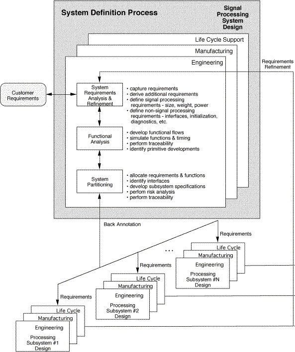
The system design process is shown in Figure 6 - 1. Top-level trade-offs are performed to determine how the system will operate and what set of subsystems are required. System-level functional and timeline simulations are developed to characterize system behavior. The output of the system design process is a set of functional, performance and physical requirements for each subsystem. As the subsystem designs progress, key subsystem parameters are back annotated, and system-level simulations are re-run to ensure that performance is maintained.

Subsystem requirements are constantly monitored to make sure the development risks are balanced among the subsystems. There is a feedback path back to the system-level from each subsystem design; this path is used whenever cost-effective subsystem designs cannot be obtained. System requirements are then reexamined and new analyses is performed to determine a refined partitioning of the requirements. By clicking on the system design process box in the IDEF figure the next level of system design can be explored. The IDEF process model of this second level will be presented and textual descriptions of each subprocess may be obtained by clicking on the text button or by clicking on the link below. This level consists of three main subprocesses:
The operational and procurement requirements are initially examined to ensure that all requirements are well understood. There is close interaction with the customer to clarify any confusion with the requirements. A traceable path must be established when requirements are allocated to functions and components. Both mission and threat analyses are performed to understand how the signal processing system should behave. The system is defined by describing the system modes, functions and interfaces. Measures of effectiveness (cost, performance, risk, testability, etc.) are established for the system to provide metrics to compare different system configurations. Operational scenarios are also develop to assist in determining system performance.
The system is decomposed into its functional elements while establishing the requirements. This functional analysis is performed by determining what functions are required to implement each system requirement. Functions are described by defining the inputs to the function, the algorithm performed by the function, and the outputs of the function. Constraints and timing requirements are identified for each function. The top-level system behavior is modeled to determine the functional performance of the system. Signal-to-noise ratios, detection ranges, probability of detection, and probability of false alarms are several examples of system-level behavior for a signal processing system. System test and maintenance concepts are developed. All functions within the system must be traced back to the system requirements.
The functions of the system are allocated to subsystems as the functional requirements are established. At this point, various system configurations are developed and characterized to determine the baseline system. Trade-off analyses are typically performed for the following areas: reliability, availability and maintainability; testability; LCC; schedule and technical risk; integrated logistics support; human factors; and system safety. All system requirements must be traceable to both functions and subsystems. The output of the system partitioning process is a set of executable specifications for each signal processing subsystem.
Other items that need to be considered during this phase of the process are considered below:
The system definition process steps of requirements analysis, functional analysis, and system partitioning are closely interrelated. The tasks shown in Figure 6 - 1 are performed concurrently, often as a series of iterations to trade-off alternative approaches and to successively provide greater detail. The system requirements are first examined before functional analysis can begin. However, the functional behavior of the system can be developed while the requirements are analyzed and refined with the customer and end-user of the system. A preliminary system functional baseline is required at the System Requirements Review. This corresponds to the first level of the spiral model. In addition, the system partitioning process begins after the initial functional baseline is identified. The limitations of various equipment configurations identified during system partitioning must be accounted for in the functional behavior simulations. The system definition process is an iterative process where requirements analysis, functional analysis, and system partitioning activities are performed concurrently to define the subsystem requirements. The system definition process is closely coupled with the architecture design activities. As the signal processor design matures, quantified processor parameters such as throughput rates and precision must be back annotated into the system-level functional simulations. In addition, the system activities continue throughout the signal processor design. The allocation of system requirements to subsystems is closely monitored to ensure that the development risks are balanced among the subsystems.
Risk management is an integral part of the system design process as sources of technical, schedule, and cost risk are identified. Risk analysis is part of all of the trade studies that are conducted. The probability of occurrence for each risk and the resulting impact on performance, development schedule, and LCC as well as their interrelationships are determined. Risk reduction plans for the risks likely to occur or those that have a critical impact on the program are generated. The key to risk management is to identify and quantify the individual risk elements so that the overall system risk can be set at an acceptable level. Another key is to track key design parameters as the system is developed to monitor the risks throughout the program. Risk management activities are formally examined during all design reviews.
Baselines are used to control the development process. The functional baseline is established following the system design phase, which prescribes:
By clicking on the system requirements analysis and refinement process box in the IDEF figure, the last level of the system design process can be explored. The IDEF process model of this third level will be presented and textual descriptions of each subprocess may be obtained by clicking on the text button or by clicking on the link below. The system requirements analysis process is composed of three primary subprocesses:
The functional analysis process describes the requirements as a set of verifiable (simulatable) statements that can be used as a basis for system design. The functions, constraints and performance statements are decomposed to a detailed level that can be allocated to specific candidate design configurations. The output of this process is a functional baseline that describes the system functionality and is the basis for eventual customer sell-off. The functional analysis process is shown in Figure 6 - 3. This process is composed of two steps, functional identification and functional decomposition, which are described in the following paragraphs.
By clicking on the functional analysis process box in the IDEF figure, the last level of the system design process can be explored. The IDEF process model of this third level will be presented and textual descriptions of each subprocess may be obtained by clicking on the text button or by clicking on the link below. The system functional analysis process is composed of three primary subprocesses:
The RASSP architecture selection process transforms the processing requirements for each processing subsystem into a candidate processing architecture of hardware and software elements. The architecture selection process overlaps with the system definition process during the later portions of the system partitioning activity. A set of executable specifications is used to transfer the signal processor requirements to the architecture selection process. A hierarchical set of simulations is performed at each design level, and the results of these simulations are back annotated in the higher-level simulations to verify that performance is maintained.
6.1.1 System Requirements Development
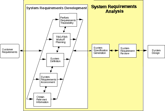
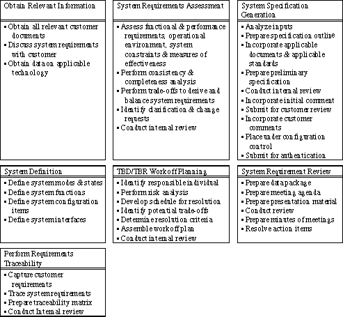
In this process step, the system requirements are checked for completeness and consistency using the steps in Figure 6 - 2. Each step is performed iteratively to determine the system requirements. A complete set of customer documents must be used to determine the system requirements because the contractor must understand how users intend to use the system. The system gets defined in terms of its system modes, states, functions, and interfaces. Trade-offs establish alternative performance and functional requirements to meet customer needs. Any potential conflicts in the trade-off results with the system requirements are resolved. A workoff plan is created for all TBD/TBR items that identifies the responsible individual, schedule for resolution, risk analysis, and key trade-offs to be performed. Traceability of system requirements and decisions ensures that the trade-off decisions made in generating the system requirements can be tracked and that these requirements are completely and accurately reflected in the final design. Traceability is also used to assess the impact of changes at any level of the system. All system-level requirements are traced to their source during this process.
--


6.1.2 System Specification Generation
The signal processing system specification contains:
It also states all necessary requirements in terms of performance, including test provisions to ensure that all requirements are achieved. Essential physical constraints and requirements for application of any known specific equipment must be included. The use of the system engineering tools, described in the system process application note, assist in automating this task.
6.1.3 System Requirements Review
A System Requirements Review (SRR) is conducted to ascertain the adequacy of the contractor's efforts in defining the processing requirements. It is conducted when a significant portion of the system functional requirements have been established.
6.2 System Design Functional Analysis
Concurrent with the establishment of the system requirements, the system configuration (the components within the processing system) is defined through iteration of the functional analysis and the system partitioning processes. Functional analysis is designed to identify the functions, decompose the functions into requirements, and allocate these requirements to lower-level functions. System partitioning takes the functions from the functional analysis process and allocates them to entities within candidate configurations. These allocations are analyzed to determine the performance, cost, and schedule impacts of the alternatives. Unsuccessful allocations and configurations are eliminated. Multiple other alternatives are carried to the next phase as the final best configuration may not be determinable until the Architecture design phase is completed.


6.2.1 Functional Identification
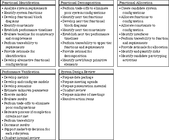
The functional identification process translates system requirements, customer heritage, and customer rationale into functional block diagrams that are used by subsequent processes to create and evaluate system configurations. This step refines and decomposes the functions identified from the system requirements analysis step. Functional identification also develops the design constraints under which the system must operate. Functional elements within the RASSP reuse library are examined to determine whether existing library elements can be used. The key steps in the functional identification process include:
6.2.2 Functional Decomposition
Functional decomposition creates lower-level functions, constraints, performance, and interfaces from those that currently exist. This more detailed information is used by the subsequent partitioning and architectural trade process. This process is structured and accomplished iteratively to eliminate poor allocation decisions as early in the analytic process as possible. Functional elements within the RASSP reuse library are examined to determine whether existing library elements can be used. If any of the system functions cannot be described by existing library elements, then we identify new primitives for development. The specific steps in functional decomposition include:
6.2.3 Informal Functional Analysis Design Review
At this time no formal design review is required with the customer. However. it is recommended that an internal informal review be conducted to examine the decomposition that has been accomplished and the initial partitioning that is concurrently being performed. This peer review ensures that requirements and functionality have not been overlooked and that assumptions are valid before beginning the architecture design process phase.
6.3 System Partitioning
During the system partitioning process, we define and evaluate candidate system configurations to determine which configurations most effectively meet the functional and system requirements. As many configurations as feasibly possible should be evaluated in enough detail to rank the alternatives. A structured method must be developed to quickly identify the feasibility of a specific candidate configuration. We typically develop measures of effectiveness for a specific program as the basis to evaluate trade studies. The output of the system partitioning process is the set of functional, performance, and physical requirements for each subsystem in the baseline configurations. For RASSP, an executable specification for each signal processing subsystem is the starting point for the architecture selection process. This executable specification is the first virtual prototype (VP0) of the subsystem. As shown in Figure 6 - 3, the system partitioning process is composed of three subprocesses: functional allocation, performance verification, and system design review. Each of these subprocesses is described in the following paragraphs.
6.3.1 Functional Allocation
The functional allocation process allocates functions from the functional block flows and constraints to entities in a specific candidate design. This process iterates until an allocated baseline can be established. This process is complete when all functions are allocated to subsystems and all requirements and constraints are mapped through functions to subsystems. This process may require many iterations to refine the system configuration. Trade-off analyses assess the risk and LCC impacts for each alternative system configuration. A key feature in RASSP methodology is the ability to quickly assess the LCC for various system configurations. Design decisions and rationale must be documented as the functions are allocated. The specific steps in the functional allocation process include: creating candidate system configurations; allocating functions and constraints to components; identifying interfaces between the subsystems; performing traceability of the system configuration to system and functional requirements; and providing the technical rationale for the functional allocation.
6.3.2 Performance Verification
The performance verification process supports the system synthesis process by providing evaluation criteria to determine which candidate configuration provides more effective performance. This effort must consider all factors of interest to the product development team: technical performance, risk, LCC, producibility, supportability, testability, etc. Critical inputs to the evaluation process are the operational concept, operational scenarios, operational maintenance concept, and usage rates expected by the user. The performance evaluation must reflect objective, demonstrable evaluation metrics and must assure the customer we considered all alternatives. The functional verification process models the allocated functions of candidate configurations to determine whether performance requirements are met. The set of mathematical elements within the RASSP reuse library is used (whenever possible) to quickly construct the functional-level simulation to verify technical performance. This process iterates with the functional allocation process until the performance of a candidate configuration meets the completion criteria established during the systems requirements analysis process. If no candidate configuration meets the completion criteria, the procedure reverts back to the functional decomposition process for an updated decomposition. If no candidate configuration meets the completion criteria for multiple decompositions, the process reverts back to the system requirements analysis process for requirement refinements. The specific steps in the performance verification process include: developing metrics, models and scenarios; configuring models; estimating unknown parameters; executing models; evaluating results; eliminating poor configurations; reiterating process if completion criteria is not met; performing traceability to requirements; documenting results; supporting the make or buy decision for each subsystem; identifying candidate prototyping activities to reduce program risk; and conducting an internal review.
6.3.3 System Design Review
A System Design Review (SDR) is conducted to ascertain the adequacy of the contractor's effort in defining the baseline system. This review is held after the performance of the candidate system configuration has been verified to meet system requirements.