Next: 8 Selected Graph Up: Appnotes Index Previous:6 Queue Data Structures
![]()
![]()
![]()
![]()
Next: 8 Selected Graph
Up: Appnotes Index
Previous:6 Queue Data Structures
The PIP has already been discussed in reference to graph state. Any computations that are involved with the setting of control variables that affect the operation of the node are called the PIP computations. This could involve the incrementing of the state counter as described in Section 4 or changing the input Node Execution Parameter (NEPS) to produce amounts on the output of the node.
The second node specialization are the NEPS (Node Execution Parameters). We have already discussed the major DF control variable called the threshold. In the basic operating mode of the DF graph a threshold is associated with the input queue. This threshold value is used to trigger the node computations downstream of the queue. When there is sufficient data or there is a block of data in the input queue of the length of the threshold, the node is fired. This amount of data is then removed from the input queue upon the completion of the node computation. In order to support a more complex operation of the DF graph we can separate the threshold in four quantities. The NEPS are:
When we were using a single threshold, we were assuming that T = R = C and O =0. However, other settings of these parameters can be used to accomplish operations that are needed for signal processing.
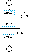
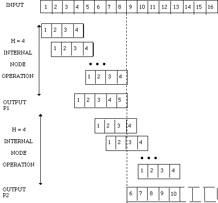
An important operation of signal processing is the Finite Impulse Response (FIR) Filter. This filter operation DF graph is shown in Figure 7-1 and the timeline of the operation of this node is shown in Figure 7-2. The input stream threshold is set, for example, to operate on 8 items and the FIR filter length is set to 4. The output as shown on the P1 output is obtained by taking the product of the first 4 input items and multiplying by the 4 hi (i = 1..4) values and summing the four products to produce the 1 output. If the entire data stream were processed in one batch then we would not require a data overlap. However, if we break up the input into blocks, the input of the preceding block must be processed to produce output for the next block of data. This produces an overlap situation. The first execution of the filter node fires when there are 8 item in the input queue, and the
node produces 5 output elements. If the NEPS were set to T=R=C then when the node fired for the second time, the 1st output from the second firing or the 6th data item overall, is a result of the node execution upon the last 3 data items from the first block and the 1st one from the second block as indicated in the tiimeline of Figure 7-2. There are two alternate methods of storing these three data items from the first computation to be used by the second firing. The first technique just stores the 3 values as a node state and set the NEPS to T=R=C. In this case the first node firing produces 5 data items and the second and subsequent times we produce 8. The data set is entirely used if the total input data length is a multiple of T=8.
The other method is to use the NEPS T=R=8 and C=5. In this case the produce amount is always P=5 until the last time. The last number of data items will not be able to be read because we do not exceed the threshold and consequently we need to have the NEPS change for the last firing of the node. By the use of NEPS we are in effect keeping the overlap data on the input queue. The selection of the method that is used for storing overlap data is dependent upon the capability of the scheduling algorithm used when the DF graph is embedded on the DSPs. Very often the use of NEPS rather than a constant threshold value and dynamically changing the values of the NEPS forces the embedded graph to actually support dynamic scheduling of the node. This increases the run time overhead. The first method which locally stores the overlap data, requires additional work to specialize the primitive for the overlap operation. From a strictly DF graph point of view, the use of NEPS explicitly shows what is being attempted in the graph rather than the technique where we use constant threshold and make primitive change to accomplish the overlap.
The inclusion of the Offset parameter in the NEPS gives the user additional flexibility to have the read amount offset from the beginning of the input data block. In this case the primitive could have been altered to read in the entire amount of O+R and then select only the R portion. This is again an effective conceptual capability that aids in the construction of the DF graph.
The last item associated with the threshold is a variable threshold. In the case of the FIR filter we have seen that there is a startup transient when the input data stream is first read. Depending upon the implementation, a change in the threshold value could occur at the beginning or at the end segment of the data set. A simple solution when using NEPS would be to preload the queue with data and thus in effect avoiding the ending transient. However, when the next input stream starts we must re-initialize the input queue and thus start the graph again. When the graph must be set up for continuous data operation of input streams of data of varying total length, the NEPS must be adjusted on a segment by segment basis and we will also need a state counter to signal when these changes in the NEPS must be made.
7.0 Primitive Construction
In a DF graph the concept of a node or primitive forms the largest reusable element in the DF graph design process. In an ideal world, any signal processing problem can be decomposed into interaction between these primitive nodes. In order to allow for customization of the primitive nodes for a particular application the concept of the PIP (Primitive Interface Procedure) as well as the NEP (Node Execution Parameters) are introduced. Their purpose is to adapt a general purpose primitive to the particular application without directly customizing the primitive code. Very often these mechanisms to customize the node are not sufficient and a new custom primitive needs to be constructed. The construction involves the creation of a new node method. 7.1 Using PIPS and NEPS
These two concepts are implemented in the interface between the core node computation module or"C"function and the DF graph directly. These two items are supported in the GEDAE™ method procedure construction. In this section we discuss the usage of this facility in the proper operation and embedding of this computation on DSP processors.


![]()
![]()
![]()
![]()
Next: 8 Selected Graph
Up: Appnotes Index
Previous:6 Queue Data Structures