Next: 4 Application of Integrated Systen Tools to SAR Benchmark Up: Appnotes Index Previous:2 Introduction
![]()
![]()
![]()
![]()
Next: 4 Application of Integrated Systen Tools to SAR Benchmark
Up: Appnotes Index
Previous:2 Introduction
It is recommended that Section 3.1.2 be read to understand what is accomplished during the signal processing system design. Section 3.2.1 entitled
"RASSP Integrated System Tool Description Overview" should then be read next to understand the capabilities of these integrated tools. One can
then read Section 3.2.2 for more details about the individual tools and Section 3.2.3 for details on their integration. However, both of these sections
may be skipped and the reader can move directly to Section 3.3 to learn the benefits of using the integrated toolset. The reader can then progress to
Section 4 to see an example how the integrated tools are used on a typical program.
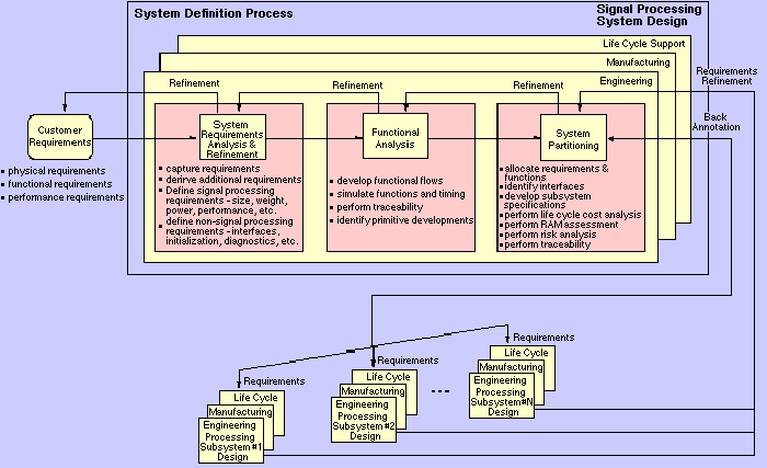
The system definition process is shown in Figure 3-2. The inputs to the system definition process include all the customer documentation detailing the processing system specification. Typical signal processing requirements include system mode functional descriptions (search, track, waveforms and algorithms), performance requirements (processing gain, timeline and precision requirements), physical constraints (size, weight, power, cost, reliability, maintainability, testability, etc.), and interface requirements. Top-level tradeoffs are performed by the multidiscipline product development team to determine how the system will operate and what set of subsystems are required. System level functional and timeline simulations are developed to characterize system behavior. The system definition process is iterative, requiring constant interaction with the customer and product development team. The outputs of the system definition process include the functional, performance and physical requirements for each signal processing subsystem.
As the subsystem designs progress, key system-level simulations are re-run to ensure that performance is maintained. The subsystem requirements are periodically monitored to make sure that the development risks are appropriately balanced among the subsystems. There is a feedback path back to the system-level from each subsystem design which is used whenever cost-effective subsystem designs cannot be obtained. When subsystem requirements can not be met, analyses are performed to determine a refined partitioning of the system requirements.
The tasks performed during requirements analysis are summarized in Table 3-1. A complete set of customer documents must be used to determine the requirements since the contractor must understand how users intend to use the system. The system is defined in terms of its modes and states, functions and interfaces. Trade-offs establish alternative performance and functional requirements to meet customer needs. Any potential conflicts
between the trade-off analysis results and the system requirements are resolved. A work-off plan for all TBD/TBR items that identify the responsible individual, schedule for resolution, risk analysis and key trade-offs to be performed is developed. Traceability of system requirements and decisions ensures that the trade-off decisions made in generating requirements can be tracked and that these requirements are completely and accurately reflected in the final design. Traceability is also used to assess the impact of changes at any level of the system. System requirements are examined to ensure completeness and consistency.
Obtain Relevant Information System Requirements Assessment System Definition TBD/TBR Work-off Planning Requirements Traceability System Specification Generation
The output of the requirements analysis task is the system specification. This specification includes the technical requirements for the system,
allocates the requirements to functional areas, documents the design constraints and defines interfaces between functional areas. This specification also
contains the necessary performance requirements. Essential physical constraints and requirements for application of any known specific equipment
which must be included in the system are included in the specification. The specification can be in either a written format, an executable format or a
combination of both formats.
The tasks performed during functional analysis are summarized in Table 3-2. The functional identification task translates
system requirements, customer heritage and customer rationale into functional block diagrams that are used by subsequent
processes to create and evaluate system configurations. This task refines and decomposes the functions identified from the
requirements analysis task. Design constraints for each functions are defined. Functional elements within the RASSP reuse
library are examined to determine whether existing functional library elements can be used.
Functional Identification Functional Decomposition
Lower level functions, constraints and performance are generated during functional decomposition. This decomposition continues until the functionality can be allocated to a specific subsystem. This more detailed information is used in the subsequent partitioning and architectural trade processes. This functional analysis is performed iteratively to eliminate poor allocation decisions as soon as possible. Functional elements within
the RASSP reuse library are examined to determine whether existing library elements can be used at this lower level decomposition. If any of the system functions can not be represented by existing library elements, new primitives are identified for development.
Traceability is established between each functional block and the system requirements.
The tasks performed during system partitioning are summarized in Table 3-3. Functions and constraints are allocated to entities in a specific candidate design during the functional allocation task. This task is completed when all functions are allocated to subsystems and all requirements and constraints are mapped through functions to subsystems. Trade-off analyses assess the risk and life cycle cost for each alternative system configuration. Design decisions and rationale must be documented as the functions are allocated. This task iterates until an allocated baseline is established. Many iterations may be needed to refine the system configuration.
Functional Allocation Performance Verification
The performance verification task supports system partitioning by providing evaluation criteria to determine which candidate configuration provides the most effective performance. This effort must consider all factors of interest to the product development team: technical performance, risk, life cycle cost, producability, supportability, testability, etc. The performance evaluation must reflect objective, demonstrable evaluation metrics and must assure the customer that sufficient candidates were considered. The behavior of candidate configurations is determined through simulation to ensure all performance requirements are met at the system level. The system partitioning process iterates with the functional allocation process until the performance of a candidate configuration meets the completion criteria established during the requirements analysis process.
The output of the system partitioning process includes the set of functional, performance and physical requirements for each subsystem. This requirements are in the form of an executable requirement and represent the first virtual prototype for the subsystem.
The RASSP architecture selection process transforms the processing requirements for each processing subsystem into a candidate architecture of hardware and software elements. The architecture selection process overlaps with the system definition process during the system partitioning activity. A hierarchical set of simulations is performed at each design level, and the results of these simulations are back annotated in the higher-level simulations to verify that overall performance is maintained.
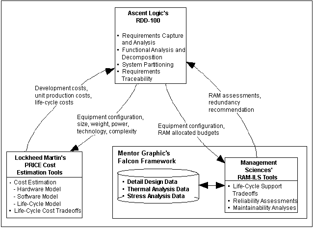
Each tool passes data to another tool through an ASCI file with the appropriate format. The types of data which are passed from one tool to another consist of the data that typically resides in that tool and can be used by the other tool. For example, system engineering data is passed from RDD-100 to the PRICE cost estimating tool. This approach eliminated the need for implementing a GUI interface for PRICE and RAM-ILS in the RDD-100 tool. The types of parameters which are passed from RDD-100 to PRICE include the equipment configuration, size, weight, power, technology and complexity factors. The development, production and support costs are calculated within the PRICE tool and these costs are back annotated into the RDD-100 data base. On the other side of the interface, the equipment configuration, allocated reliability and maintainability budgets, and cost data are passed from RDD-100 to the RAM-ILS toolset. The reliability and maintainability assessment is performed within the MSI toolset and the results of these analyses are back annotated into the RDD-100 data base. In addition, optimizations can be performed within the RAM-ILS toolset when the reliability requirements are not met and the tool can make a recommendation on how redundancy can be added in the system in the most cost effective way to meet the requirements.
Now that you have a basic understanding of the integrated toolset, you may read Sections 3.2.2 and 3.2.3 for more detailed information on the
individual tools and their integration. For a shortened version you can skip directly to Section 3.3 to read about the benefits of using these tools in a
cooperative manner.
RDD-100 is based upon an entity, relationship and attribute (ERA) database. Entities within the database are the nouns or objects within the system
such as requirements, functions and components. The interrelationship between different entity types are defined by an extendible schema within
RDD-100. It is through these relationships that traceability is maintained within RDD-100. The base RDD-100 schema has been extended for
RASSP to support the integrated costing and reliability analysis and these extensions are described in Section 3.2.3.1.
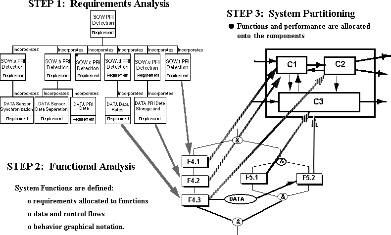
The typical use of RDD-100 is illustrated in Figure 3-4. Requirements are initially captured, examined and decomposed into lower level requirements
during the requirements analysis step. The functionality of the system is then defined using behavior diagrams within RDD-100 during the functional
analysis step. Both control and data flow are shown within the same behavior diagram. Every function within the behavior diagram must be traceable
to a requirement. The physical architecture consisting of hardware and software components is established during the system partitioning step. Each
function in the behavior diagram must be allocated to one component in the system architecture. A traceable path between each function and the
component that function is allocated to is maintained within RDD-100.
The PRICE cost estimating tools consist of the hardware, microcircuit, hardware life cycle and software models and each of these models are described
below.
PRICE H - Hardware Cost Model : The hardware model is used to estimate the cost and schedule for electronic, electro-mechanical, and structural
assemblies. This model incorporates input data concerning weight, size, quantity, process and design sensitivity, and complexity parameters. The
hardware model provides cost and schedule outputs for the development and production phases of a program.
PRICE M - Microcircuit/Module Cost Model : The microcircuit model is used to estimate the cost and schedule for custom microcircuits, printed
circuit boards, and electronic modules. The model uses functional relationships based upon parameters such as the number of transistors, percentage
of new circuit cells, number of pins, board types and size.
PRICE HL - Hardware Life Cycle Model : The hardware life-cycle model is used to estimate the cost of operating and maintaining hardware systems
throughout their deployment. Inputs to the life cycle model include deployment parameters, maintenance concepts, cost, and escalation factors. The
life cycle model is a supplement to and works in conjunction with the hardware model.
PRICE S - Software/Software Life Cycle Model : This software model is used to estimate the cost and schedule for the design, development,
integration, testing, and support of software. This model uses functional relationships based upon parameters such as function, lines of code,
complexity, platform, application, and design reuse to estimate costs.
PRICE Systems refine and update their cost estimating models based upon actual costs being incurred on current products of their users. While the
cost models are designed to provide estimates for a typical organization, the models provide the flexibility for the user to tailor and calibrate the
models for their specific organization. As a result of calibration, the costs and schedule outputs of the models reflect how a particular organization
develops their product.
The PRICE model requires that the system be described as a set of hardware and software components in an equipment breakdown structure (EBS)
which is shown in Figure 3-5. Parameters which characterize each component are entered into the model. Global parameters which define labor rates,
financial factors and deployment concepts are also required. The PRICE models determines the development, production and support costs for each
component in the EBS and these costs are accumulated up the equipment tree to determine the overall system costs.
Design Assurance Tool Value Added Functional Reliability Risk Allocation Reliability goals for hardware and software Circuit Based Design Reliability Simulation Stress derating for component selection Functional Reliability and Longevity Analysis Improved performance in operational life cycle Deployment Life Cycle Cost Tradeoffs Economic and warranty analysis Failure Modes and Effects Criticality Analysis Safety and degraded performance analysis Diagnosability and Repairability Maintenance requirements analysis Mission and Deployment Reliability Durability, capability and performance analysis Maintainability and Supportability Support staff/equipment requirements analysis Worst Case Analysis (Aging and Degradation) Parametric degradation analysis Thermal Damage Analysis Thermal derating analysis
The RAM-ILS toolset can be used for reliability predictions, maintenance analysis, failure modes and effects criticality analysis (FMECA), and
success tree analysis. Each of these capabilities are described below.
Reliability Predictions - Reliability predictions are made within the RAM-ILS tool using reliability block diagrams. Failure models for each
component in the system can be based upon relevant historical data, specialty computational methods, probability distributions and "similar to"
designs. These predictions facilitate trade-off studies when allocating failure rate budgets to system components.
Maintainability Predictions - The RAM-ILS tool can be used to determine the impact of various maintenance concepts on life cycle cost. The tool
models various maintenance strategies such as level of repair and fault isolation characteristics. Maintenance diagrams are constructed within the
toolset.
Failure Modes and Effects Criticality Analysis (FMECA) - The FMECA portion of the RAM-ILS toolset provides the user with an understanding
how the system will perform when it is operating in either a degraded or failed state.
Success Trees - Success trees are modeled within the RAM-ILS toolset to illustrate how a system successfully operates with respect to the
interaction of system functions and components. Inverted success trees identify unacceptable critical combinational failures. Success trees can be used
to confirm redundancy decisions and identify false redundancy conditions.
The RAM-ILS toolset is integrated with Mentor Graphics Falcon Framework and is illustrated in Figure 3-6. This integration provides a consistent,
well-defined, known user interface. As a result, the user does not need to learn another specialized interface to use the RAM-ILS tool. In addition, the
Mentor interface provides convenient access to detailed design data.
Type of Attribute Attribute
Comment Component Characterization Parameters Quantity Parameters
Physical Parameters Power Parameters Sensitivity Parameters Hardware Technology Parameters Software Parameters Software Characterization Parameters
Type of Attribute Attribute Comment Development Cost Parameters Production Cost Parameters Operational Cost Parameters Support Cost Parameters Sensitivity Cost Parameters
Type of Attribute Attribute Comment Reliability Parameters Maintainability Parameters Maintenance Concept Parameters
Type of Attribute Attribute Comment Operational Parameters System ‘ility Parameters Deployment Parameters Sensitivity Parameters
The attributes for the duplicate component entity are essentially identical to the additional attributes added to the component entity in the RASSP
extended schema. The major difference between the attributes is that the various quantity attributes in the component entity have been replaced by the
total system quantity attribute in the duplicate component entity. The total system quantity attribute contains the total number of identical
components used within one system and this number is calculated and back annotated into the RDD-100 database by running the "Calculate Total
System Quantity Report" within RDD-100.
Type of Attribute Attribute Comment PRICE File Parameters RAM-ILS File Parameter
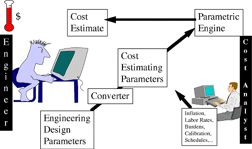
An automated Integrated Design To Cost (IDTC) environment has been developed which enables engineers and cost estimators to work efficiently
together using their native tools so many design alternatives can be examined during system concept trade-off studies. As shown in Figure 3-8, the
engineer works within his system engineering tool (RDD-100) to enter a physical description of a potential design. This information is then exported
out of the system engineering tool and read into the cost estimating tool(PRICE). The data is then translated into cost estimating parameters and
merged with information from the cost analyst to produce a complete set of data for the parametric estimating engine. The parametric engine produces
a cost and schedule estimate and exports this data back to the system engineering tool. The engineer can then access this cost data within the system
engineering tool.
This IDTC estimating process is an improvement to the traditional method in many ways. It is faster, enabling more alternatives to be explored. It is
more accurate and repeatable because the estimating relationships are controlled by the estimator, codified into a language script and executed by a
computer. Since the relationships are codified, the engineer does not need to meet with the estimator every time a cost estimate is needed. This IDTC
process allows the engineer and estimator to work effectively together. A cost estimate can be turned around in minutes instead of days or weeks with
this IDTC environment.
The organization of this section is as follows. The physical elements of the IDTC environment are initially described. Then the process to use the
IDTC environment is explained.
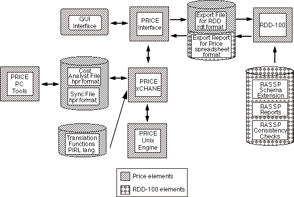
The RASSP IDTC environment consists of the RDD-100 and PRICE extensions as shown in Figure 3-9. The schema, consistency checks and
output reports have been developed for RDD-100 which support the IDTC environment. A cost analyst file, synchronization file, PRICE Rule
Language (PRL) import template, and PRL export template have been developed within the PRICE Enterprise toolset to support the automated
IDTC environment. The use of each of these elements within the IDTC environment is described below. Note that the parameters calculated by the
RAM-ILS tool which are used within PRICE to support cost estimating are not explicitly shown in Figure 3-9, since these parameters are back
annotated into the RDD-100 database prior to using them in PRICE.
The schema within RDD-100 has been extended on the RASSP program to support both cost estimating and reliability analysis as previously
described in section 3.2.3.1. The engineer populates the RDD-100 data base with the system engineering parameters that define the physical
configuration of the hardware and software. A consistency report is then executed within RDD-100 to make sure that the database has been sufficiently populated to obtain a cost estimate. An export report is then run within RDD-100 which
outputs the system configuration with all the required attributes in the appropriate format (format needed by the PRICE tool is defined in the interface
specification) to import into the PRICE cost estimating tools. The cost for each system component is then estimated within the PRICE tool based
upon the system engineering parameters and data provided by the cost analyst. The PRICE tool generates an output file in the standard RDD-100 rdt
format which contains the development, production and support costs for each system component. This cost data is populated within the RDD-100
data base using the standard RDD-100 import facility.
Cost Analysis File - The cost analyst file is used in conjunction with the RDD-100 output file, PRL import template and the synchronization file
to establish all of the parameters the PRICE tool needs to perform a cost estimate. The cost analyst file contains default parameters for each
component in the system which are missing from translation of the RDD-100 file. The parameters typically defined within the cost analyst file are
prototype and production schedule, labor rates, escalation rates and other financial factors that the PRICE tool needs. The information is entered
within the cost analyst file on an element type basis. Each component within the PRICE estimating breakdown structure has a particular element
type such as electro-mechanical, software and design integration. All components of the same mode type receive the same default parameters
contained within the cost analyst file if the parameter is missing from the RDD-100 file and synchronization file.
Synchronization File - The synchronization file is used in conjunction with the RDD-100 output file, PRL import template and the cost analyst
file to establish all of the parameters the PRICE tool needs to perform a cost estimate. The synchronization file contains parameters for each
component which override any parameter from either the translation of the RDD-100 file or cost analyst file. It is through the use of the
synchronization file that the cost analyst can control the cost estimate since any parameter within this file will supersede the same parameter from
any other source. The information is entered within the synchronization file on a component name basis which enables each component to have its
own parameters within the synchronization file. Since the PRICE interface has been designed to interface with multiple tools, a lock file name is
used within the PRICE tool to identify which parameters are active for overriding parameters for each tool interface. It is through the use of the lock
file name that the same synchronization file can be used for interfacing PRICE to multiple tools.
PRL Import Template - System engineering parameters within RDD-100 are used to populate attributes within the PRICE toolset. However, there
is not a direct one-to-one mapping of the system engineering parameters within RDD-100 to PRICE attributes. A simple illustration of this is that
the length, depth and width of a component are entered in RDD-100 for a hardware component, while the PRICE tool only uses volume. As a result,
the system engineering parameters must be translated into attributes understood by the PRICE tool. A proprietary interpreted language called PRICE
Rule Language (PRL) was developed to translate parameters from other tools into PRICE attributes. As a part of the RASSP program, a PRL
import template was written which translates approximately 65 system engineering parameters for each component into about the same number of
PRICE attributes. This import template was developed for the signal processing domain, although it may be applicable to digital hardware and
software systems. To support other domains, additional translations are required that are unique to that particular domain.
PRL Export Template - Development, production and support costs for each component are back annotated from the PRICE tool into the RDD-100
database. A PRL export template is used to write the cost data out of the PRICE tool into a file with the appropriate format. In this case, the
standard RDD-100 rdt format is used so that the data can be imported into RDD-100 with the standard import mechanism.
Each of these process steps is described below. Note that this process is iterative in nature and is repeated as the system design matures, resulting in
more accurate cost estimates.
Create Parametric Estimating Relationships - The parametric estimating relationships (PER) which are used to convert system engineering data into
PRICE cost estimating attributes are established and codified into the PRICE Rule Language (PRL) during this process step. This process step is
performed once and should address all product lines and application domains which IDTC is intended to be used. The generation of the PRL import
template should be done once for a company and is not typically part of a specific project. The PER's and PRL import template are updated to reflect
changes in a company's product line. The cost estimating department is responsible for developing the PER's. The process used to generate these
relationships are contained within a company's work instructions. These relationships are developed from legacy data from previous projects. The
output of this process step is the PRL import template which codifies the rules to translate RDD-100 system engineering parameters into PRICE
attributes. The RDD-100 schema, consistency checks and export reports may need to be modified if additional system engineering parameters are
needed to characterize a company's product.
Analyze Project's Programmatic Requirements - The customer requirements are analyzed in this process step to determine whether a company is
going to proceed in bidding the program. The program management and proposal response teams perform this process step using the company's
legacy data and conceptual baseline architecture for the project. The outputs of this process step include the job instructions for conducting the project
and the set of allocated budgets for the program.
Create the Cost Analyst File - The cost analyst file used to supply default parameters while importing system engineering parameters into the
PRICE tool is created during this process step. The cost estimating department is responsible for the generation of this file using the PRICE tool.
This file contains default parameters which are used to supplement the attributes obtained from the translation of the RDD-100 parameters. This file
typically contains prototype and production schedules, labor rates, escalation rates and other financial factors.
Develop and Verify System Architectures - Architecture tradeoffs are performed during this process step to determine the hardware and software
elements of the system. This process step is performed by the IPDT team which must consider all aspects of the system life cycle. The IPDT
performs this process step using the allocated budgets, project technical information and cost data in determining the composition of the system. The
requirements are analyzed, the system functions are decomposed and system architectures are analyzed using RDD-100. This process step is iterative
in nature and is repeated for each candidate system design. The output of this process is the system configuration with costing data. The fidelity of
the cost data can either be comparative in nature, rough order of magnitude or basis of estimate depending upon the rigor used in developing the
parametric estimating relationships.
Obtain the Cost Estimate - The development, production and support costs for a system architecture are determined during this process step. This
process step is performed by importing the RDD-100 generated file containing the system engineering parameters using the PRL import template,
cost analyst file and synchronization file into the PRICE Enterprise toolset. The outputs of this process step are the cost reports from the PRICE
tool and the ASCI file containing the development, production and support costs. This file is used to import the cost data into the RDD-100
database.
Create and Maintain the Synchronization File - The synchronization file used to supply overriding parameters while importing system engineering
parameters into the PRICE tool is created during this process step. The cost estimating department is responsible for generating this file using the
PRICE tool. This file contains overriding parameters which supersede the values obtained from either the translation of the system engineering data
or cost analyst file. This file provides the mechanism that the cost analyst can use to control the cost estimate.
Management Sciences, Inc. (MSI) RAM tools provide a new approach to applying traditional "ilities" design techniques early in the design process.
The goal of using RAM tools early in the system engineering effort is to reduce the number of nasty surprises encountered later in the product life
cycle. It is in this early design phase that the most reliability improvements can be recognized and incorporated cost effectively. Through the early
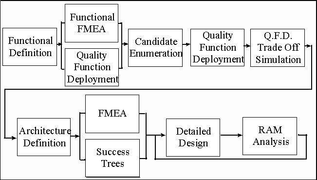
use of the integrated systems tools, reliability requirements and issues are identified and documented cooperatively and concurrently with other design
requirements and issues as shown in Figure 3-12. Thus, quality related issues can be applied to the architecture selection process, and issues and
requirements can be documented, tracked, and monitored through the product design life cycle.
The remainder of this section provides a short discussion of the software integration with Ascent Logic's (ALC) RDD-100 tool. This discussion is
followed with a description of how the MSI tools support the RASSP systems engineering process. The MSI tools that are discussed include:
Quality Function Deployment (QFD), Failure Modes and Effects Analysis (FMEA), and Integrated RAM Analysis. Through reading this section,
you will obtain an understanding of the benefits of using these capabilities early in the design process.
The systems engineer populates the RDD-100 data base with the equipment configurations, functional descriptions, interface items and allocated
RAM budgets. An export report is run within RDD-100 which outputs the system configuration and its associated attributes in the appropriate
format for the MSI RAM toolset. The specialty engineer uses this data within the MSI toolset with detailed CAD data from existing designs to
support a variety of RAM analyses such as Quality Function Deployment (QFD), Failure Modes and Effects Analysis (FMEA) and RAM
assessment. The predicted RAM attributes calculated by the MSI toolset are back populated within the RDD-100 data base.
Components, functions and interface items defined within the RDD-100 data base are used to initially populate a FMEA data base within the MSI toolset. The specialty engineer can then use this FMEA data base to perform the following tasks:
The integrated system tools provide an efficient process for the engineer to access cost data. Engineers can obtain complete life cycle costs using the
system tools without becoming an expert cost analyst. The integrated system tools provide an environment which can be effectively used to
implement either Design To Cost (DTC) or Cost as an Independent Variable (CAIV) programs which are being emphasized within DoD. The cost
estimation process has been established so the cost analyst is able to control the estimate.
The integrated system tools provide a reliability and maintainability analysis capability throughout the design process. These tools provide the
mechanism that allows specialty engineers to be involved early in the design process. The RAM-ILS tool provides capabilities to perform reliability,
maintainability, success tree and FMECA analyses. In addition, the system architecture can be optimized to meet reliability requirements in a cost
effective fashion with the integrated system tools.
3.0 Technical Description
3.1 RASSP Systems Engineering Process
3.1.1 Overview
The RASSP design process consists of the signal processing system-level design, architecture selection and detailed hardware/software design as shown in Figure 3-1. The inputs to the RASSP design process are the physical, functional and performance requirements for the signal processing system. These requirements typically are passed down from the platform system level design which is performed prior to the signal processor design. During the signal processing system design, the requirements are captured and analyzed, the functional behavior of the system is defined and the requirements and functions are allocated to the major subsystems of the signal processor. Hardware/software co-design activities are performed during the architecture selection process and a virtual prototype of the system is developed. Once the processing architectures are determined, the hardware and software are developed and integrated during the detailed design process. Note that these processes are iterative in nature and that feedback between the processes is used whenever required. The focus of this section of the application note is to describe the RASSP systems engineering process. 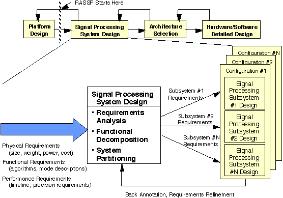
3.1.2 RASSP System Process Description
The RASSP system definition process is a front-end engineering task in which signal processing concepts that meet customer requirements are developed and top-level trade-offs are performed to determine the processing subsystem requirements. Although the same type of functional decomposition and allocation is performed as in the traditional design process, several significant RASSP extensions have been developed which lead to shorter design cycles. Emphasis is placed on understanding the life cycle impact of early design decisions in the RASSP process. Each member of the integrated product development team participates in the system-level tradeoffs to ensure that the complete life cycle is considered during the design process. Model year architecture concepts are used in RASSP designs to ensure that the signal processor can easily be upgraded to support its entire life cycle. Emphasis is placed on making early design decisions so prototyping activities can begin early in the program to reduce high-risk elements. The output of the system definition process is a set of executable specifications that have the requirements for each processing subsystem in an executable form. The executable specifications support the RASSP concept of reuse and minimize errors due to human interpretation. Traceable system requirements are passed via executable specifications from the system definition process to the architecture design process. As the design progresses, the ability to meet requirements is passed back to the system-level simulations so the impact of lower-level trade-offs are analyzed.
3.1.2.1 Requirements Analysis
During requirements analysis a user need is converted into a set of system requirements that satisfies that need. Customer documentation is reviewed and discussions are held with the customer and user to refine the purpose and manner in which users will operate the system. The focus of system requirements analysis is to determine what the system is to do and how the system is to be used. External interfaces to the system are identified. Methods to verify each requirement statement are determined. This process iterates with the functional analysis and system partitioning efforts to assess feasibility and to structure the requirements cost-effectively. This iteration also makes the verification process more accurate and cost effective by eliminating ambiguity in the requirement statements.
3.1.2.2 Functional Analysis
During functional analysis, the system is decomposed into its functional elements. This analysis is performed by determining
what functions are required to implement each system requirement. Functions are described by defining the inputs to the
function, the algorithm performed by the function and the outputs of the function. Constraints and timing requirements are
established for each function. The top-level functional behavior is modeled to ensure that the functional requirements are met.
3.1.2.3 System Partitioning
During system partitioning, candidate system configurations are defined and evaluated to determine which configurations most effectively meet the functional and system requirements. As many configurations as feasibly possible should be evaluated in enough detail to rank the alternatives. A structured method must be followed to quickly identify the feasibility of a specific configuration. The output of the system partitioning process is the set of functional, performance and physical requirements for each subsystem in the baseline configuration.
3.2 RASSP Integrated System Tools Description
3.2.1 Overview
The ATL RASSP team has developed a concurrent engineering environment based upon COTS tools which supports the RASSP systems engineering process. This concurrent engineering environment, which is shown in Figure 3-3, consists of Ascent Logic Corporation's (ALC)RDD-100 system engineering tool, Lockheed Martin PRICE Systems cost estimation tools and Management Sciences' (MSI) RAM-ILS toolset. RDD-100 is used to capture and analyze the requirements, to define the functional behavior of the system, to allocate the requirements and functions to the subsystems, and to provide requirements traceability. PRICE cost estimating tools are used to estimate the development, production and support costs for the processing system. The RAM-ILS tool is used to perform reliability and maintainability analyses.
3.2.2 Individual Tool Description
3.2.2.1 RDD-100
Ascent Logic Corporation's (ALC) RDD-100 is a system engineering tool used for capturing requirements, relating the requirements to a behavior
model, and allocating the functionality to a physical architecture. The tool supports object-oriented analysis, stimulus response threads, and other
analysis techniques. RDD-100 can be used to produce specifications at the system, segment and/or component level. Traceability of all system level
parameters from both requirements to functions and from functions to components is maintained within RDD-100,
3.2.2.2 PRICE Cost Estimating Tools
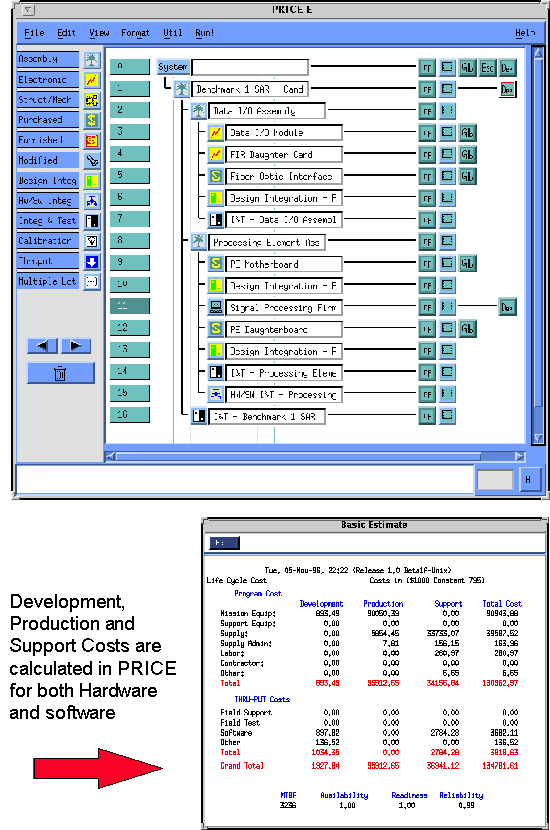
Lockheed Martin's PRICE Systems cost estimating models are advanced Computer Aided Parametric Estimating (CAPE) tools used for calculating
cost estimates and schedules for both hardware and software components. Computer-aided parametric estimating tools are parametric cost models that
relate physical and empirical system characteristics to the costs and schedules required to develop, produce and maintain the system. These cost
estimating relationships (CERs) are embodied within the computer model. PRICE Systems formalizes these relationships by applying regression
techniques to hardware and software systems across various industries. In addition, these estimating relationships can be calibrated for a specific
organization so the outputs obtained from the PRICE tools reflect that organization's costs.
3.2.2.3 RAM-ILS
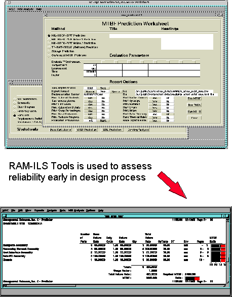
Management Sciences Incorporated's (MSI) RAM-ILS toolset provides design assurance management for an overall system design environment. The RAM-ILS toolset consists of synergistic tools within the design framework which measure the quality related aspects of a design. This toolset is used to assess the functional robustness, functional reliability, functional diagnosability, manufacturing process reliability, and deployment reliability issues. The features of the RAM-ILS toolset are summarized in Table 3-4.
3.2.3 Integrated Tools Description
3.2.3.1 RASSP Schema Extension Overview
The schema within RDD-100 has been extended on the RASSP program to support both cost estimating and specialty engineering. An overview of
the RASSP schema extensions is presented in this section to give the reader a basic understanding of these modifications. For more detailed
information on the schema extensions see the RDD-100 User's Manual for the Integrated System Engineering RASSP Schema and the
"Specification for Ascent Logic Corporation, RDD-100 Schema Extensions (for the RASSP program)".
The baseline RDD-100 schema has been extended in six basic areas to support cost estimating and specialty engineering.
Each of these schema extensions is described below.
3.2.3.1.1 Additional Component Attributes
Additional attributes have been added to the component entity in the RASSP schema to characterize the component for cost and reliability
assessment. A summary of these additional attributes is given in Table 3-6. Some of these attributes are not applicable to all component types. For
example, the attributes which characterize software are not applicable to purely hardware components.
3.2.3.1.2 Cost Entity
The attributes in the cost entity primarily contain the development, production and support costs, which are back annotated from the PRICE tool
into the RDD-100 database. There must be one cost entity for each component in the equipment tree, which is related to the component by the
"costs" relationship. A summary of the cost entity attributes is given in Table 3-7. The budgeted costs in this table are entered by the user and
represent the cost requirement. The predicted costs are calculated by the PRICE tool and are back annotated into RDD-100.
3.2.3.1.3 RMA Entity
The attributes in the RMA entity primarily contain reliability and maintainability metrics which are back annotated from the RAM-ILS tool into the
RDD-100 database. There must be one RMA entity for each component in the equipment tree which is related to the component by the "has rma"
relationship. A summary of the RMA entity attributes is given in Table 3-8. The budgeted RMA attributes in this table are entered by the user and
represent the allocated requirement. The predicted RMA attributes are calculated by the RAM-ILS tool and are back annotated into RDD-100
3.2.3.1.4 Life Cycle Parameter
The attributes in the life cycle parameter entity characterizes the operational environment and deployment scenario for the product under development.
There must be one life cycle parameter entity defined for the system which is related to the system component through the "satisfies" relationship. A
summary of the life cycle parameter attributes is given in Table 3-9.
3.2.3.1.5 Duplicate Component
A component may be replicated in multiple places within the system equipment tree. Since each instance of a component entity must have a unique
name in RDD-100, a means of identifying which components are identical is needed to ensure that the appropriate development, production and
support costs are calculated within the PRICE toolset. The duplicate component entity is used to identify families of components that are identical
and are built from different parent components. The relationship "includes duplicate" is made from the duplicate component entity to all identical
components within a family. Note that when identical components have the same parent within the equipment tree, the attribute entitled "Quantity in
Next High Assembly" is used to reflect the number of identical components used in the parent and the use of the duplicate component is not needed
for this case.
3.2.3.1.6 External Tool File Entity
The attributes in the external tool file entity contains information about file location for both the PRICE and RAM-ILS tool. A summary of the
external tool file attributes is given in Table 3-10.
3.2.3.2 Integrated Design To Cost
3.2.3.2.1 Overview
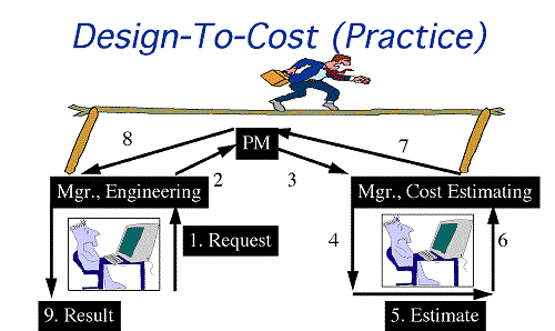
Traditional cost estimating processes have relied upon estimators and engineers to work within a functionally-oriented organizational process, as
shown in Figure 3-7. As a result, the traditional process is slow, inconsistent and generally not repeatable. From the cost estimator's perspective, the
costing process is a top-down process that requires the translation of engineering specifications into cost model inputs and an estimating breakdown
structure (EBS), and the execution of the model to obtain preliminary results. These results are then iterated back to engineering several times to
resolve any questions that arise. From the engineer's perspective, the traditional costing process is a bottoms-up process that requires the creation of
an engineering estimate based upon labor hours and a bill of materials supported by vendor quotes. Generally, these two estimates are compared and a
resolution is reached via a process that varies from company to company. Although this process may be valuable in providing cost perspectives from
two different approaches, this process has proven to be much too slow and costly to be responsive in using cost as a design trade-off parameter in a
Design To Cost (DTC) environment.
3.2.3.2.2 IDTC Environment
3.2.3.2.3 IDTC Process
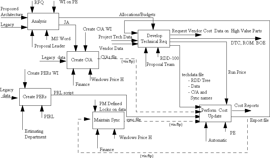
The process in which the IDTC team can effectively implement IDTC is shown in an IDEF3 representation in Figure 3-10. This process diagram is
an adaptation of the process used by one of the beta site companies evaluating the RASSP integrated system tools. Each box in this figure represents
a process step. The inputs to the process are shown on the left side of the box, the control parameters on the top, the resources needed for the process
on the bottom and the output of the process on the right side. The IDTC process consists of six steps which are listed below:
3.2.3.3 RAM (Reliability, Availability and Maintainability) Assessment
3.2.3.3.1 Overview
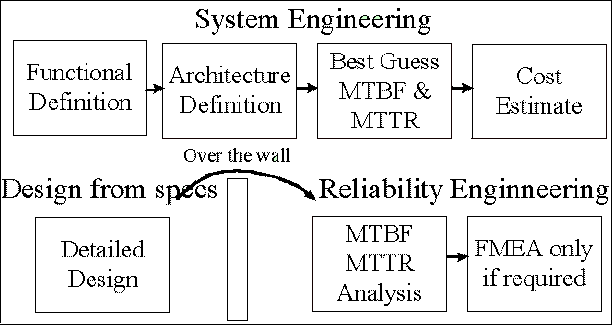
Traditional RAM engineering processes are disjoint with respect to the product development cycle as shown in Figure 3-11.
Reliability engineering has typically been viewed as a necessary evil; a very time consuming effort to be left to specialty
engineers. While most engineers have a basic understanding of quality goals and issues, much of the focus in implementing
quality has been on the statistical aspects of quality rather than applying reliability knowledge in the engineering design effort.
Problems associated with this traditional approach are listed below:
3.2.3.3.2 Software Integration
The RMA entity type has been added to the RDD100 schema (as described previously in Section 3.2.3.1) to support a combination of reliability
analysis, documentation, and statistical analysis. This entity type contains statistical values such as MTBF, Reliability, MTTR, and Availability
which are used in performing integrated cost estimating and detailed statistical reliability analysis.
3.2.3.3.3 Quality Function Deployment (QFD)
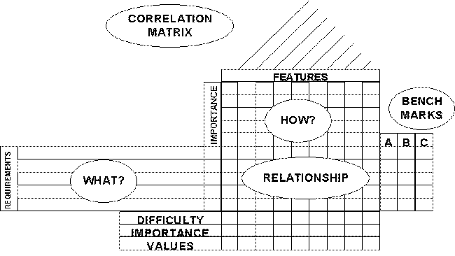
The relationship among the requirements, architecture candidates and customer expectations can be depicted in Quality
Function Deployment models. These QFD charts (typically referred to as "House of Quality") show a correlation between
what must be done, how to do it, and the relative benefits of each candidate architecture as shown in Figure 3-13. Functions,
components and interface items within the RDD-100 data base can be used to populate various elements within the QFD
spreadsheet template in the MSI toolset at the indenture level desired. A different chart is created for each function or
component within the system. The specialty engineer can then populate the remaining items of this spreadsheet when
performing the QFD analysis.
3.2.3.3.4 Failure Modes Effects Analysis (FMEA)
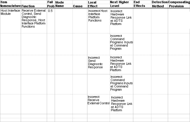
FMEA models define the relationship between components, functions and failures in meeting mission performance
requirements. FMEA spreadsheets depict a correlation matrix between how things fail, how the failures will be detected, and
what is likely to happen in the event of a failure. The engineer uses this analysis to understand these relationships early in the
design and to make changes to the architecture candidate that facilitate a safer, more maintainable, and more reliable system.
An example of a FMEA spreadsheet populated automatically from the RDD-100 data base is shown in Figure 3-14. Data items that are missing from the worksheet must be manually populated by the engineer.
3.2.3.3.5 Integrated RAM Analysis
RAM models define the relationship between architecture candidates, failure probabilities, availability, and repair times. The
components hierarchy and allocated RAM defined within the RDD-100 data base are used to populate the MSI RAM toolset.
This toolset can be then used for the following tasks:
The RAM predictions within the MSI toolset are based upon the data populated from RDD-100 and data the user adds within
the RAM tools. Typical sources for MTBF and MTTR values used for the system engineering activities are estimates of
acceptable loss rate, "similar to" designs, historical data and vendor data. The results of the RAM assessments within the MSI
toolset are back annotated in the RDD-100 data base.
3.3 Benefits of Using the RASSP Integrated System Tools
The integrated system tools provide a concurrent engineering environment where tradeoffs considering a product's complete life cycle are performed.
Multi-disciplinary design data is stored in one location that the entire IPDT team can assess. As a result, the entire design team uses the same data
within their analyses which eliminates the confusion when parameters are maintained in multiple locations. Cost performance tradeoffs are performed
using the integrated tools to optimize the system design over multiple disciplines. The integrated tools provide a quick impact analysis capability, as
detailed design data can be used to update the reliability and cost predictions.
![]()
![]()
![]()
![]()
Next: 4 Application of Integrated Systen Tools to SAR Benchmark
Up: Appnotes Index
Previous:2 Introduction