Next: 3 Summary Up: Appnotes Index Previous: 1 Introduction
![]()
![]()
![]()
![]()
Next: 3 Summary
Up: Appnotes Index
Previous: 1 Introduction
The PDMS is used for configuration management of all design data produced during the design and implementation cycles. The design data is organized by projects within the PDMS and managed according to the rules and conditions defined in the
RASSP CM Model [CM_VERSION_3_96]. Access to design data stored within the PDMS is governed by the user roles and authorizations defined in the RASSP Authorization Model document [AM_VERSION2_94]. Additional details of these models are available in the indicated references or in the Information Management Application Note.
Several user roles are identified in the RASSP Authorization Model implementation for the specific demonstration projects. Two of these roles support administrator and user functions. Administrator functions are associated with project
management, for example creating and deleting projects, creating groups, creating users, assigning users to groups, assigning users and groups to projects, assigning user roles and authorizations, and creating project vaults and workspaces.
User functions are associated with execution of a project. These include data creation, data registration, data check-in and checkout, and generating problem reports and change requests. Both administrator and user functions are performed through
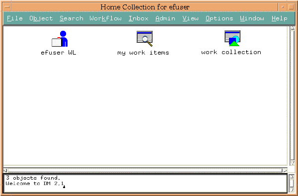
the PDMS user interface. The RASSP Home Collection user interface for the PDMS user efuser is shown in figure 2 - 1. Icons in the Home Collection represent the following:
Detailed definition of the functions and capabilities of the PDMS implementation for RASSP is provided in the productdocumentation developed by Intergraph. The relevant documents include:
IDEF3 models were also developed enabling analysis and validation with commercial process simulation tools. In order to apply the models to projects, the IDEF models were implemented as workflows in the Workflow Management System.
Utilizing IDEF methodologies enables maintenance of the process models in a tool independent format - allowing maximum flexibility in application of the models in multiple projects, groups, or organizations. Additional information on IDEF3X and
processing modeling is available in the Process Modeling Application Note
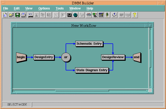
Workflows are constructed using DMM Builder (Figure 2 - 3) by selecting the components (tasks, terminals, and operators) from the pull-down menus, placing them in the window, and connecting them with precedence links. The precedence links govern the order in which workflow tasks are executed. Once the workflow has been constructed, it is compiled and saved as a file in a directory. These workflow files can be viewed as repeatable templates that are attached to projects as needed. DMM Attacher is the utility that attaches workflow templates to projects, and DMM Detacher is the utility that removes workflow templates from completed projects.
The functionality of DMM and the Workflow Management System also consists of administrator and user functions. Administrator functions include creating workflows, and attaching and detaching workflows from projects. Operations with
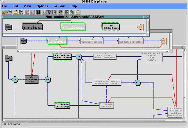
DMM Builder, DMM Attacher, and DMM Detacher are normally considered administrative functions. User functions generally involve execution of workflows that are attached to projects using DMM Displayer (Figure 2 - 4). Workflows are
executed in DMM Displayer by placing the cursor on a workflow task that's startable and double-clicking the left mouse button. A dashed green border highlights startable tasks. When a workflow task is executed, its status changes to in-progress and is then highlighted by a solid green border. When the task is completed, its color changes to a dark gray. The workflow is considered complete when the status of all the tasks is complete.
More detailed informaion on the functions and capabilities of Design Methodology Manager is available from Design Methodology Manager Users Guide.
DMM Builder was used to construct workflows for the design phases of RASSP using information represented in the IDEF3X models. These workflows were organized as templates, and managed in a repository for application to projects. Table 2 - 1 summarizes the process models, and workflows developed for each of the RASSP design phases.
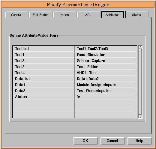
Autoscript is a custom application developed as an extension of the Workflow Management System specifically for interaction with the Product Data Management System. Autoscript is invoked when a workflow task is executed. At runtime it generates an execution script for the task, based on attributes defined for the task. These attributes, Datalist and ToolList are defined for each workflow task when the workflow is constructed in DMM Builder.
The DataList and ToolList attributes are defined in the Attributes folder, as illustrated in the DMM dialog box of figure 2- 5 for each workflow task. The command line that executes Autoscript is specified in the Action folder. Information on states, and exit status for the tasks are also specified in the corresponding folders. A complete description on the syntax for defining DataList and ToolList attributes, a description of the data required in all of the folders, as well as more information about Autoscript, DMCLI, and Toolpad, is contained in Integrated Computer Aided Manufacturing DEFinition (IDEF) and the Design Methodology Manager Users Guide.
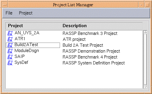
When PLM is invoked, it displays a list of available pre-assigned projects available to the user based on assigned role. For an administrator or project manager (highest level of access privilege) all available projects would be displayed. In the example shown in PLM window figure 2 - 6, the user has access to six projects: AN_UYS_2A, ATR1, Build2ATest, ModuleDsgn, SAIP, and SysDef. Selection of a project is performed with mouse clicks.
When a workflow project is selected for execution by a user, PLM will invoke both the DMM Displayer using the top-level workflow, and the AIM Product Data Management System. This combination the user with access to the relevant task information in the workflow, and the corresponding data items for the tasks.
A benefit provided by the CAD tool encapsulation strategy is that the specific tool setup and initialization requirements environment (environment variable setups, etc.) are handled by the workflow encapsulation manager - simplifying the requirements for the user. Tool launch is accomplished by a mouse click on the tool icon in the Toolpad display.
CAD tool encapsulations were developed for multiple tools and applications on the RASSP program, for support of multiple benchmark programs, demonstrations, and beta site users. Table 2 - 2 summarizes the tool encapsulations developed, and as a result are available for application to programs.
Detailed information on the Syntax and semantics of the tool encapsulation files is provided in [TOOLENCAP_96], the Tool Encapsulation Specification.
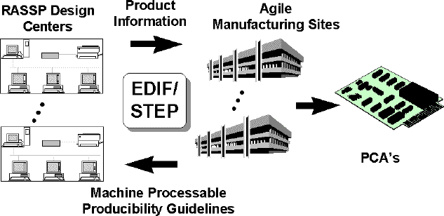
The Manufacturing Interface is composed of several distinct tools. The Manufacturing Resource Editor (MRE) is used to capture the capabilities of a manufacturing facility in standard form. The Mentor-to-STEP Data Converter
tool is used to convert Mentor design files into standard STEP files. The STEP product data is used by a Producibility Advisor in conjunction with manufacturing capability information captured by the MRE to determine
any issues against the design based on the manufacturing production line chosen. The product data and manufacturing capabilities are also used by the Process Planner to create a manufacturing process plan. Manufacturing and design engineer interaction via the Web-based Access Mechanism and collaboration tools
enables rapid resolution of issues at early design phases. More detailed information on the RASSP Manufacturing interface is provided in Manufacturing Interface Application Note
A prototype of the Reuse Data Manager was developed by Sandpiper Software, Inc. (point of contact Elisa Finnie [(408) 868 - 9731] used to demonstrate distributed access to multiple distributed repositories of VHDL models in April 1998. The core technologies developed by Sandpiper Software, Inc. will be offered as commercial products in late 1998. More detailed information on the RASSP reuse strategy, the architecture of the Reuse Data Manager, and VHDL model application and other applications is provided in Reuse Application Note
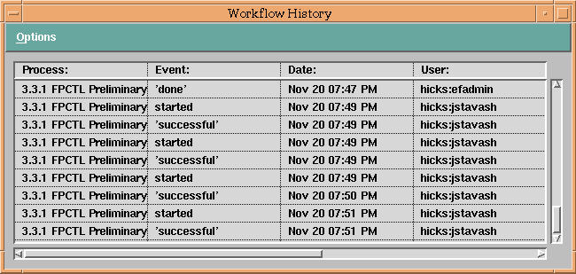
The Workflow Management System records the project history, which includes the workflow task names, the start and stop time of each workflow task, user names associated with tasks, and task completion status as indicated in
figure 2 - 8. In addition, the Workflow Management System tracks the scheduled start & stop dates for each workflow task, information on the relationship of scheduled events and actual events is readily available to project
engineers and managers. The status logs from the Workflow Management System are also exportable in a formatted text for use by other project tools such as MS Project.
The logging information is recorded in a transaction file. Additional post processing is performed using this information to produce summary reports detailing specific metrics associated with persons, CAD tool, and process
steps. Total time spent in a CAD tool is a metric of interest which is derived from the status logs.
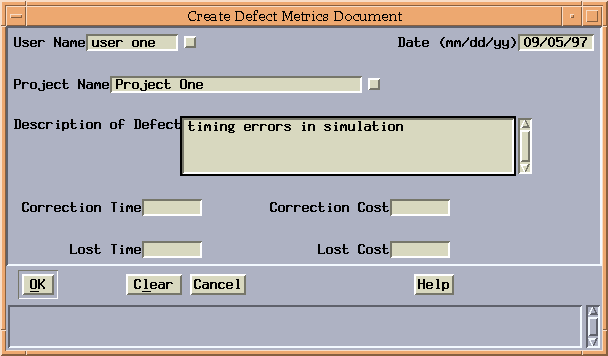
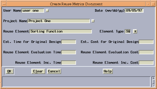
In addition to the Workflow Management metrics collection, a metrics support utility was developed for the Product Data Management System. This supports additional metrics such as: design defects, reuse data and personal logs.
Figure 2 - 9 and 2 - 10 illustrate the custom user interface screens supporting this utility.
The Metaphase screen for defect information includes the date, user's name, project name, description of the defect,
and the time and cost associated with correcting that defect.
The Metaphase screen for reuse information includes the date, user's name, project name, reuse element, the element type, and the time and cost associated with incorporating that reuse element into the current project.
2.0 Technology Description
The core technologies associated with the Enterprise Framework include the product data management system, workflow management system, reuse management system, and the manufacturing interface. Commercial tools are used where suitable capability exists, augmented with new capabilities and features as appropriate. This section summarizes the architecture of each of these systems, and details the key enhancements developed on the RASSP effort.
2.1 Product Data Management System
Intergraph's Asset & Information Manager (AIM) is used to implement the Product Data Management System (PDMS) within the RASSP Enterprise Framework. The AIM implementation used on RASSP uses Metaphase, version 2.1, as the underlying architecture. Metaphase uses an embedded Oracle relational database and offers a scaleable client/server architecture, an object-oriented data model, and rules-based processing. Additional features were developed and added to AIM in order to meet the PDMS requirements for the RASSP program. These additional features include:
2.2 Process Modeling
LM-ATL developed process models for the design phases of RASSP using the IDEF3X and IDEF3 modeling methods. IDEF3X, developed by Rockwell International Corporation, is an extended version of the Integrated Computer Aided
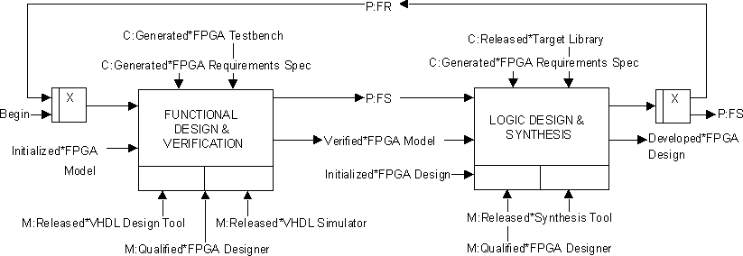
Manufacturing DEFinition (IDEF) language Number 3 [IDEF]. An IDEF3X example is provided in figure 2 - 2. IDEF3X combines
the ICOM (Input, Control, Output, and Mechanism) feature of IDEF0, the process flow description of IDEF3, and additional annotation features to facilitate implementation by a workflow management tool. The syntactic elements of an
IDEF3X model are similar to IDEF3 and include units of behavior (UOBs), junction boxes, and precedence links. Additional features include:
2.3 Workflow Management System
Intergraph's Design Methodology Manager (DMM) is used to implement the Workflow Management System within the RASSP Enterprise Framework. DMM is a graphical workflow management tool with capability for construction and execution of workflows. Key discriminating features of DMM are support for hierarchical workflows, flexibility in implementation of tool and data item management schemes, and management support capabilities (metrics logging and interaction with project management tools). The components of DMM are:
Design Phase IDEF3X Model DMM Workflow System Design X Requirements Analysis
X X Functional Analysis
X X System Partitioning
X X Architecture Design X Functional Design
X X Architecture Selection
X X Architecture Verification
X X Detailed Design X X X X X X X X X X X X X X X X X X X X X X X X X X X X X X X X X X X X 2.3.1 Autoscript, DMCLI, and Toolpad
Functional enhancements to the workflow management tool consist of capability enhancements and integration with the AIM Product Data Management system. Autoscript and DMCLI (DM Command Line Intepreter) are RASSP products developed by Intergraph Corporation which implement the Workflow to PDM interaction. Another RASSP product, Toolpad, enhances the flexibility of DMM in tool and data item control during execution of an
individual workflow step.
2.3.2 Project List Manager
Project List Manager (PLM) is a custom application, developed by Intergraph Corporation, for management of reusable workflow segments and previously developed project plan workflows. It also manages active or in-process workflows.
2.3.3 CAD Tool Encapsulations
Encapsulation of CAD tools with the enterprise framework is accomplished by generation of an encapsulation file for each tool, which is referenced by the execution scripts produced dynamically during workflow execution. The encapsulation files are ASCII files which contain the necessary environment settings required to launch the tool (e.g. environment variables, path settings, command line arguments, etc.), and are stored in a designated tool
information directory. The encapsulation file names, are specified as ToolList attributes for workflow tasks in which the tool is to be invoked. For example, in the Workflow Task Attributes Folder, shown in figure 2 - 5, Func-Simulator, Schem-Capture, Text-Editor, and VHDL-Tool are names of tool encapsulation files.
2.3.4 Manufacturing Interface
To achieve the goal of first-pass manufacturing success, the RASSP Manufacturing Interface (Figure 2 - 7) provides seamless integration of design and manufacturing as well as supporting an IPDE. By enabling real time design interaction between engineering and manufacturing, the Manufacturing Interface allows virtual and real prototypes to be produced quickly, and with significantly improved quality. The RASSP Manufacturing Interface effort encompassed several related industry efforts including: industry funded PDES, Inc. Electrical project, the ATP-funded PreAmp program, the DARPA-funded ASEM MCM efforts, the TRP-funded CommerceNet program, and others.
2.3.5 Reuse Data Management System (RDMS)
Reuse data management within the Enterprise Framework involves the release, cataloging, and searching of reusable design objects. Sources of reusable design objects include CAD tool libraries, CAD tool independent libraries, vendor component data books, and design objects created within a design organization. The approach for
reuse data management consists of:
2.3.6 Metrics
Metrics collection and analysis capabilities are provided with the RASSP enterprise framework, to provide improved program management capabilities in collection and analysis of key productivity metrics. Metrics capability
enables better identification of bottlenecks and problem areas in the current design processes, facilitates updates of the design process to improve cycle time, and aids in verification of the anticipated productivity improvements.
![]()
![]()
![]()
![]()
Next: 3 Summary
Up: Appnotes Index
Previous: 1 Introduction