Next: 6 Autocoding Tool Evaluations Up: Appnotes Index Previous:4 Top Level Command Program Architecture
![]()
![]()
![]()
![]()
Next: 6 Autocoding Tool Evaluations
Up: Appnotes Index
Previous:4 Top Level Command Program Architecture
The first part of this section will address the abstraction problem while the second part will show how the prototype Application Specific Interface Builder (AIB) interfaces to GEDAE™ to generate the ASI.
As noted in Section 3.0, What is a Command Program, the Command Program Interface (CPI) layer of the command
program provides a set of generic controls over the application graphs to the command program. Since this is a Commercial-off-the-shelf (COTS) interface to the CP, it contains no application specific information. Nor does it reveal anything about the specific set of graphs that compose an application or the specific set of parameters and queues that
are to be controlled by the CP. Furthermore, the CPI interface is defined in terms of abstractions that are natural to the signal processing data-flow model of computation - graphs, queues, graph parameters.
However, the UI and EFSM layers are expecting Command and Control System (CCS) abstractions. Suppose a sonar application has two major waveforms (abstractions), called WAV1 and WAV2. The operator that interacts with the CP wants to be able to issue commands to the CP like "Do WAV1" or "Do WAV2". The operator does not care that WAV1 processing requires the dynamically coupling of several graphs together and configuring them via a collection of parameters. Those are signal processing abstractions. Figure 5 - 1, Application Specific Interface Bridges the Gap between
Data Flow Abstractions and Control Flow Abstractions, illustrates the tension between the view of the SPP presented by the CPI and the view of the signal processing program desired by the CCS. The role of the ASI layer is to translate
between data flow abstractions and control flow abstractions.
ASI formalizes control flow abstractions by introducing the concepts of mode and submode as the primary ASI layer abstractions. A mode is a collection of one or more related (typically connected by dynamic queues) top level graphs, their associated dynamic queues and their graph execution control parameters that are to be controlled by the CP and
that will be instantiated and de-instantiated together. A submode is a subset of the graphs within the mode. They contain a specific dynamic queue linkage topology and a specific set of values for a subset of the control parameters. A submode transition consists of transforming the old submode queue topology into the new submode queue topology, conditionally reinitializing graphs, and loading the submode specific set of parameter values.
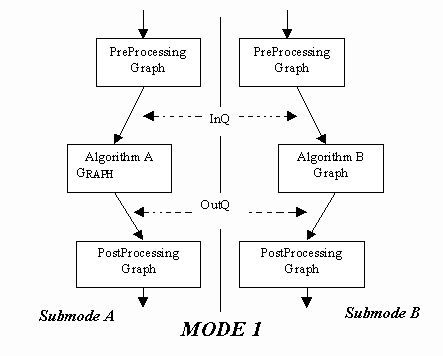
Consider for example Figure 5 - 2, Mode and Submode are Primary ASI Layer Abstractions. Mode 1 contains four graphs - PreProcess, PostProcess, Algorithm A, Algorithm B - and two dynamic queues - InQ, OutQ. It is decomposed into
two submodes - SubmodeA and SubmodeB. All four of the graphs and the queues shown are instantiated on entry to Mode 1. During graph instantiation the queues are configured for the default submode, say SubmodeA. Transitioning
from SubmodeA to SubmodeB consists of disconnecting InQ and OutQ from Algorithm A and reconnecting them to Algorithm B. Although not shown on the figure, there may be parameters for any of the graphs that also need to be loaded on the submode transition. For example there could be a parameter for PostProcessing that reconfigures a
switch or a threshold internal to that graph. All queues and graphs are destroyed when Mode 1 is exited.
The mode / submode abstractions allow the ASI layer to present the interface shown in Table 5 - 1, Application Specific Interface. The functions provide for simple mode and submode changes and mode execution control. Notice also that the ASI layer "personalizes" the parameters and queues that are to be read by the CP. A function binding the application specific name and datatype is provided for each parameter and queue.
5.0 BUILDING the application specific interface
The challenge to autocoding the Application Specific Interface (ASI) layer of the command program is:

|
ASI Function |
Description |
|
enter_<mode_name> |
Reads launch package(s); initializes H/W; loads launch package(s) ; obtains handles for params |
|
exit_<mode_name> |
Kills launch package(s) |
|
startSmd_<mode_name> |
Pauses execution; reconfigures queues; loads parameter set file(s) |
|
run_<mode_name> |
Enables graph processes for execution; Download "set" values to graphs; Enables output and input data flow |
|
pas_<mode_name> |
Disables input data flow and waits for graph pipeline to clear |
|
cont_<mode_name> |
Continues input data flow (after a pause) |
|
rst_<mode_name> |
Resets launch packages and queues to default configuration |
|
stp_<mode_name> |
Disables graph process execution |
|
mdState_<mode_name> |
Returns current mode |
|
smdState_<mode_name> |
Returns current submode |
|
exState_<mode_name> |
Returns current execution state |
|
set<parameter_name> |
Makes value available for graph download on next run command |
|
wr<parameter_name> |
Immediately downloads value to graph |
|
rdCur<parameter_name> |
Reads value currently being used by graph |
|
rdSet<parameter_name> |
Reads value currently pending download to graph |
|
rdq<queue_name> |
Read specified number of tokens from queue |
|
wrq<queue_name> |
Write specified number of tokens to queue |
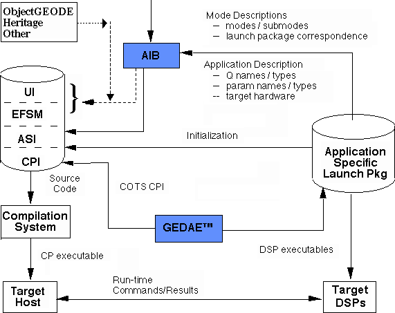
Application Specific Interface Builder (AIB) is the prototype tool used to construct the ASI. AIB's inputs and integration with GEDAE™ are shown in Figure 5 - 3, System Software Developed with AIB/GEDAE™. The first step in constructing the ASI is to develop graphs using the GEDAE™ development environment. Once the graphs are completed and tested in the GEDAE™ environment, GEDAE™ will build an application specific launch package. The launch package contains the DSP executables as well as corollary information needed for program instantiation and initialization. The AIB user provides a small text file describing the mode/launch package association and the submode queue topology and parameter set filename. The launch package corollary information is readable by AIB and provides AIB with a description of all queue and parameter names and their data types. AIB then constructs the ASI functions, which can then be integrated with EFSM and UI level source code to complete the CP.
![]()
![]()
![]()
![]()
Next: 6 Autocoding Tool Evaluations
Up: Appnotes Index
Previous:4 Top Level Command Program Architecture