|
 
Using Altera MegaWizard Components in FPGA Compiler II and FPGA Express
Alan Ma
Senior Corporate Applications Engineer
Synopsys, Inc.
alanma@synopsys.com
(2000.9.11)
Introduction
The advancement in capacity of Field Programmable Gate Arrays (FPGAs) has made design reuse an integral part in high-density FPGA designs. In order to meet time-to-market requirements, designers are turning to predesigned, verified, and synthesizable functions ranging from adders, multipliers, shifters, to larger and more complex functions such as FIFOs.
Altera's MegaWizard Plug-In Manager, or MegaWizard for short, helps designers create or modify predesigned and verified components that contain custom megafunction variations. These custom megafunction variations are based on Altera-provided megafunctions, such as Library of Parameterized Modules (LPMs), which are optimized for Altera architecture. The MegaWizard is a utility that helps designers easily specify options for the custom megafunction variations. The utility asks questions about
optional ports and the values designers want to set for parameters. The results are "plug-and-play" components that can improve the quality of the designs in less time.
This document describes how MegaWizard-generated components can be used in the Synopsys?FPGA Compiler II and FPGA Express (FCII/FE) environment. FCII/FE includes architecture-specific FPGA synthesis technology and FCII is the only solution for million-gate designs with the addition of several advanced features as well as Synopsys design flow compatibility. The FCII/FE technology provides superior results in both area and speed performance and is further enhanced with the support for MegaWizard
components.
A MegaWizard component for RAM, LPM_RAM_DQ, will be used as an example throughout this document. The new megafunctions for APEX20KE devices, namely ALTCLKLOCK, ALTLVDS, and ALTCAM, will be just briefly mentioned due to their similarities to LPMs. In all cases, examples in both Verilog and VHDL will be given. It is assumed that the readers have basic knowledge of creating a component using MegaWizard and synthesizing a simple design in FCII/FE.
The Process at a Glance
Using MegaWizard-generated components in FCII/FE consists of the following steps:
- Creating the MegaWizard component in Verilog or VHDL
- Instantiating the MegaWizard "wrapper"
- Synthesizing the design, without the actual MegaWizard component, in FCII/FE
- Exporting the netlist in FCII/FE
- Placement-and-routing of the entire design
Let us discuss each of these steps in detail.
Creating the MegaWizard Component in Verilog or VHDL
In Quartus, selecting Tools in the menu and then MegaWizard Plug-In Manager will launch the utility. In MAX+plus II, the same can be accomplished by selecting File and then MegaWizard Plug-In Manager. What MegaWizard typically does is create a top level design, or "wrapper", in which an LPM with the functionality that best fits the designer's requirements is instantiated. Throughout this document a MegaWizard-generated RAM component will be used to illustrate the design flow. Since
LPM_RAM_DQ will be the underlying LPM used, the "wrapper" will be named use_lpm_ram_dq. Figure 1 shows that use_lpm_ram_dq can be written in AHDL, Verilog, or VHDL. Only components created in Verilog or VHDL will be discussed in this document.
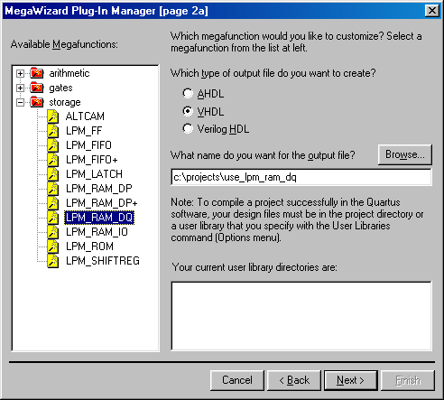
Figure 1 Creating a RAM in MegaWizard Plug-In Manager
Instantiating the MegaWizard "Wrapper"
After the MegaWizard component has been created, the next step is to instantiate it in the design. In Verilog, the process involves direct instantiation of the "wrapper" and an empty module to provide the port direction information. Figure 2 shows a sample Verilog design. Note that the empty module is required in FCII/FE and it should be included at the end of the design file in which the "wrapper" is instantiated.
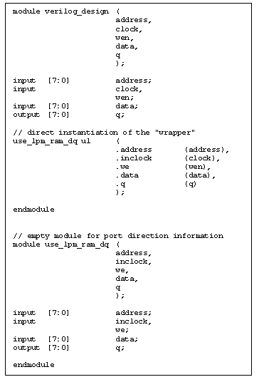
Figure 2 Sample Verilog Design
The process is very similar in VHDL, which involves direct instantiation of the "wrapper" and a component declaration to provide the port direction information. Figure 3 shows the equivalent design in VHDL.
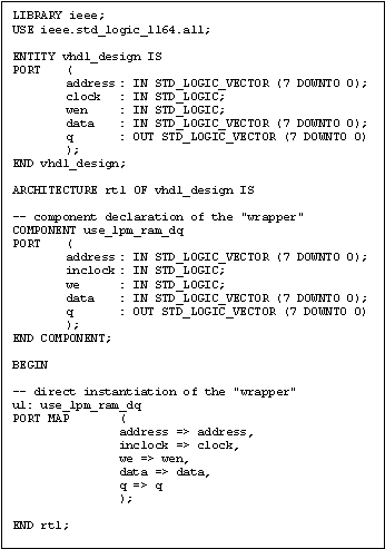
Figure 3 Sample VHDL Design
In either case, the port names for correct instantiation can be obtained from viewing the "wrapper".
Synthesizing the Design, without the Actual MegaWizard Component, in FCII/FE
Create a project in FCII/FE and add the design to the project. It is important that the MegaWizard-generated components, such as use_lpm_ram_dq.v or use_lpm_ram_dq.vhd, are NOT added to the project. Doing so leads FCII/FE to treat the instantiated MegaWizard component as a black-box during elaboration. If the design is written in VHDL, FPGA Compiler II will generate the following warning messages:
Warning: Cannot link cell 'vhdl_design/u1' to its reference design 'use_lpm_ram_dq'. (FPGA-LINK-2)
Warning: The cell '/vhdl_design/u1' is not linked to any design. (FPGA-CHECK-4)
The above messages will not appear if the design is written in Verilog because of the presence of the empty module.
The next step for FCII/FE is to optimize the elaborated design for the target technology. Please refer to the FPGA Compiler II Getting Started or the FPGA Express Getting Started for more information on elaboration and optimization.
Exporting the Netlist in FCII/FE
Once the design has been elaborated and optimized, a netlist can be exported for place-and-route. This can be done by right-clicking on the optimized chip in the Chips window of the FCII/FE Graphical User Interface (GUI) and selecting Export Netlist. Figure 4 shows the Export Netlist dialog box.
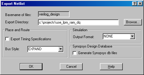
Figure 4 Exporting Netlists in FCII/FE
Placement-and-Routing of the Entire Design
The MegaWizard-generated components, such as use_lpm_ram_dq.v or use_lpm_ram_dq.vhd, should be placed in the same directory specified by Export Directory in the Export Netlist dialog box (Figure 4). This directory should be used as the project directory of Quartus or MAX+plus II. It is important that the top level design file, for example, verilog_design.v or vhdl_design.vhd, is specified as such in the place-and-route tools. Quartus or MAX+plus II will then be
able to link the MegaWizard-generated components and proceed to place-and-route the entire design.
Instantiating LPMs Directly in the Design
While the MegaWizard Plug-In Manager is an excellent utility to create or modify custom megafunction variations, designers also enjoy the flexibility of instantiating LPMs and passing parameters to them in Verilog or VHDL. There is a file named lpm_components.vhd, located in < FCII/FE directory>\lib\packages\Lpm, which contains port name and parameter information of all the LPMs supported by FCII/FE. Figure 5 shows the section for LPM_RAM_DQ in lpm_components.vhd.
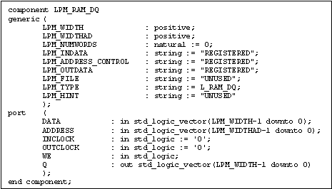
Figure 5 LPM_RAM_DQ Component Declaration
In Verilog, FCII/FE requires all LPM parameters to be specified using the #() construct. They are also required to be listed in the same order as they appear in lpm_components.vhd. In Figure 6, the order in which the LPM parameters are passed matches precisely with what is shown in Figure 5. Note that although the parameter LPM_HINT is not used its value "UNUSED" is still required inside the #() construct. As mentioned previously, an empty module is needed to provide port
direction information.
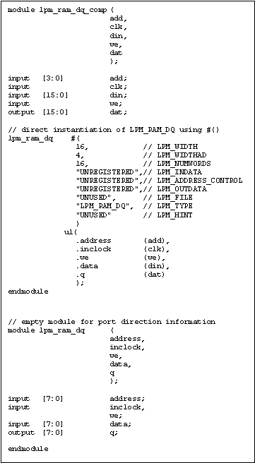
Figure 6 Instantiating LPMs in Verilog
When instantiating LPMs in VHDL, FCII/FE does not require all LPM parameters to be listed as long as the names of the ones being used in the GENERIC MAP section match with their counterpart in lpm_components.vhd. Furthermore, a component declaration is not needed when the following statements are included in the design:
LIBRARY lpm;
USE lpm.lpm_components.all;
Figure 7 illustrates an example. Note that the unused parameters LPM_FILE and LPM_HINT are not listed in the GENERIC MAP section.
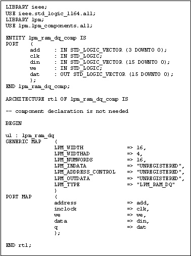
Figure 7 Instantiating LPMs in VHDL
It is important to understand that when LPMs are directly instantiated in a design, only the ones with names that have the prefix LPM_ are supported in FCII/FE. This also holds true for LPM parameters.
New Altera Megafunctions for APEX20KE Devices
FCII/FE version 3.3.1 supports the new megafunctions for Altera's APEX20KE devices, namely ALTCLKLOCK, ALTLVDS, and ALTCAM. The recommended black-boxing methodology for LPMs remains the preferred design flow for these megafunctions. It is therefore not repeated here.
In situations where these megafunctions are instantiated in the design the same precaution as discussed for LPMs applies. The only part that requires special attention is Export Netlist. The current default bus style in FCII/FE is EXPAND. It has to be changed to %s[%d:%d] for Altera's Quartus to place-and-route the FCII/FE-generated netlist successfully. Figure 8 shows the modified Bus Style field.
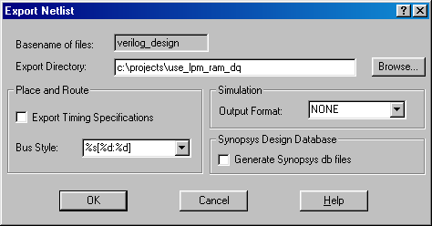
Figure 8 Bus Style Requirement of Altera's Quartus
Note that this procedure is only needed when ALTCLKLOCK, ALTLVDS, or ALTCAM are instantiated. The black-boxing methodology does not require the bus style to be changed and therefore it is the recommended design flow.
Additional Information
This document is intended to focus specifically on using MegaWizard-generated components in FCII/FE. Please refer to the FPGA Compiler II Getting Started, FPGA Express Getting Started, or the on-line help for additional information on how to use other features of FCII/FE.
For up-to-date technical information, please:
For general information on Synopsys design tools, please visit http://www.synopsys.com.
Summary
The goal of this article is to describe how Synopsys FPGA Compiler II and FPGA Express can help designers improve productivity by taking advantage of Altera's MegaWizard components in FPGA designs. The MegaWizard is a utility that helps designers easily specify options for custom megafunction variations. These parameterizable and synthesizable components are proven to reduce designers?time-to-market.
Whether the design is written in Verilog or VHDL, the recommended methodology is instantiate the MegaWizard-generated components as black-boxes. FPGA Compiler II/FPGA Express is then used to synthesize the design and generate a netlist. Altera's Quartus or MAX+plus II will link the netlist and the MegaWizard-generated components during the place-and-route process.
LPMs can also be directly instantiated in a design. Both Verilog and VHDL examples are discussed.
FPGA Compiler II/FPGA Express version 3.3.1 supports the new megafunctions for Altera's APEX20KE devices. The recommended black-boxing methodology certainly applies well to ALTCLKLOCK, ALTLVDS, and ALTCAM. In situations where these megafunctions are instantiated in the design the same precaution as discussed for LPMs applies. However, special attention needs to be paid to the bus style when exporting netlists. The default EXPAND has to be changed to %s[%d:%d] for Altera's Quartus to successfully
place-and-route the FPGA Compiler II/FPGA Express-generated netlists.
|
![]()