Next: 3 RASSP Manufacturing Interface Usage Scenarios Up: Appnotes Index Previous: 1 Introduction
![]()
![]()
![]()
![]()
Next: 3 RASSP Manufacturing Interface Usage Scenarios
Up: Appnotes Index
Previous: 1 Introduction
getmentordesign [design_directory_name]
This command acquires and renames Mentor Board Station PCA design files.
The files are acquired from <design_directory_name>, renamed,
and placed in the current working directory. Once these operations
are complete, the PCA design data is accessible to mentor2step.
The get-mentor-design script acquires the following MGC PCA design
files from the <design_directory_name>/pcb directory:
The get-mentor-design script copies the PCA design files to the
directory where the script is executing and changes their names to the
following, respectively:
mentor2step [d q pd v vv sm -do_report
-nsa -ss] [pf <output_step_file>]
mentor2step [er ecad_step_file] [d q pd v vv
sm -do_report -ss]
[pf <output_step_file>]
Executing mentor2step with no arguments causes it to print out
a description of the available options. Mentor2step converts Mentor
Board Station PCA design data files into a file that conforms syntactically
to the STEP Part 21 (ISO/IS 1030321) specification and semantically
to the STEP Application Protocol 210 specification.
mentor2ap210 [mentor2step options] [output_file_name]
[mentor_design_directory_name]
The mentor2ap210 script acquires MGC PCA design data by executing
get-mentor-design (discussed in Section 2). It then executes the
mentor2step data converter to translate the MGC PCA design data
to AP210 format.
edif400l0_to_ap210 [-d -q -v] <input_file_name> [<output_file_name>]
Executing the command with no arguments causes a description of available
options to be printed. If an output file name is not provided, the automatically
generated file name will have the following structure: <input_file_name>.step.
Since there will always be a single input file, the user interface of
this data converter is significantly simpler than the one that provides
support for Mentor Board Station.
The RASSP Manufacturing Interface currently provides support for Mitron's
CIMBridge, a system which provides the kind of manufacturing support described
above. Design information is entered into the CIMBridge system via a file
format called GenCAD. The RASSP-MI supports this system by synthesizing
GenCAD file from PCA design data represented in STEP AP210 form. This is
shown in Figure 2.2-1
a2g [-d -q -v -vv] [-sr <STEP AP210 File Name>] [-gf <GenCAD File
Name>]
A description of the options and defaults of a2g is printed if
the program is executed with no arguments.
This Section discusses the relationships between each of the above items.
Also, the information captured for each item is explained.
This rest of this section is organized as follows. Section 2.3.1 discusses
operational aspects of the MRE. Section 2.3.2 provides the user with factory
configuration guidelines. Advice is provided to assist the user in making
effective and efficient use of the MRE. More detail concerning the operation
of the MRE can be found in the Build I Manufacturing Interface User's Manual[SCRA95].
2.0 Technology Description
The following Sections discuss both the purpose and operational details
of the components that make up the RASSP-MI.
2.1 Input Interfaces
The following Sections discuss two interfaces that import electronic design
data into the RASSP-MI that have been developed. The first imports design
data created by Mentor Graphics Corporation's Board Station PCA design
product. The second imports design data represented by the EDIF 4 0 0 (Level
0) standard. The mechanism by which Mentor Board Station and EDIF 4 0 0
are supported is by converting these data representations into the STEP
AP210 standard PCA design data representation. STEP AP210 is the representation
used internally by RASSP-MI components. The same approach can be used to
add support to the RASSP-MI for other electronic CAD (ECAD) systems and
standards as necessary.
2.1.1 Support for Mentor Graphics Corporation's Board Station
Support for PCA design information created using Mentor's Board Station
product is provided by The Mentor Board Station to STEP Application
Protocol 210 (AP210) EXPRESS Driven Data Converter[Hin94]. This Section
discusses the operation of this data converter in detail. Figure 2.1.1-1
presents a data flow diagram that illustrates how the data converter operates
and how it fits into the overall RASSP-MI system. The definition of "RASSP
Manufacturing Interface Core Capabilities" is all functions of the RASSP-MI
that perform operations other than facilitating input and output.
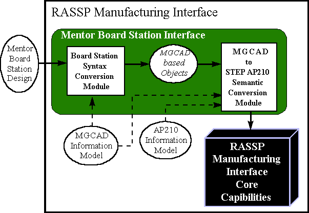
The Mentor Board Station Interface is implemented by the mentor2step
executable. This program is assisted by two C-shell scripts that collect
Mentor Board Station data files and simplify the user interface for the
most common usage of the data converter. The remainder of this Section
discusses the operation of these components in detail.
2.1.1.1 Mentor Board Station PCA Design File Preparation using getmentordesign
The getmentordesign script prepares Mentor Board Station
PCA design files for use by mentor2step. The calling syntax of this
command is as follows:
These files normally occur under the pcb directory except for ascii_parts_file,
which can be generated from within the Board Station LAYOUT tool. The <max>
notation indicates the largest integer for all files matching the pattern
name.name_<integer>.
The mentor2step module uses these files directly.
2.1.1.2 Mentor Board Station PCA Design Data Conversion Using mentor2step
The mentor2step data converter converts Mentor Board Station design
data into STEP AP210 format. The calling syntax of the data converter is
as follows:
2.1.1.3 Mentor Board Station PCA Design Data Conversion Using mentor2ap210
Mentor2ap210 is the top-level script that automates much of the
Mentor Board Station to AP210 data conversion process. The calling syntax
of this module is as follows:
2.1.2 Support for EDIF 4 0 0 Level 0
PCA design data represented in EDIF 4 0 0 Level 0 form is supported in
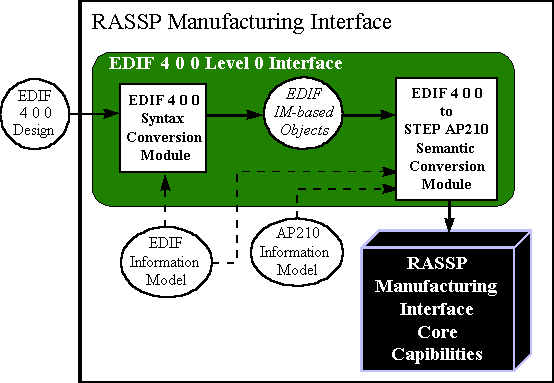
the RASSP-MI. Figure 2.1.2-1 shows how the EDIF 4 0 0 Level 0 Interface
fits into the RASSP-MI architecturally as well as the interface's internal
architecture and data flow. The EDIF 4 0 0 file format is first converted
into its EDIF 4 0 0 Information Model equivalent. The Information Model
is represented in the EXPRESS[ISO94] data modeling language, making it
possible to apply the EXPRESS Driven Data Conversion technique. This technique
was used in the development of the EDIF 4 0 0 to STEP AP210 Semantic
Conversion Module. Currently, only the subset of EDIF 4 0 0 Level 0
necessary to generate GenCAD data files (discussed in Section 2.2) is supported
by the RASSP-MI. It is expected that the coverage of the data converter
will be expanded in the future. Areas of coverage that would be useful to
add include functional (gate-level) and pin swapping information.
The syntax of the data converter is as follows:
2.2 Output Interfaces
Once an electronic design has been completed and released to a manufacturing
facility for production, a significant amount of information remains to
be generated based upon the design to be manufactured. For example, Numeric
Control (NC) programs must be generated to guide the operation of automatic
component placement equipment. Many other types of manufacturing machines
on the production line also require NC programs or parameter files to guide
their operation. In addition, automatic testing equipment requires detailed
knowledge of the design in order to operate correctly.
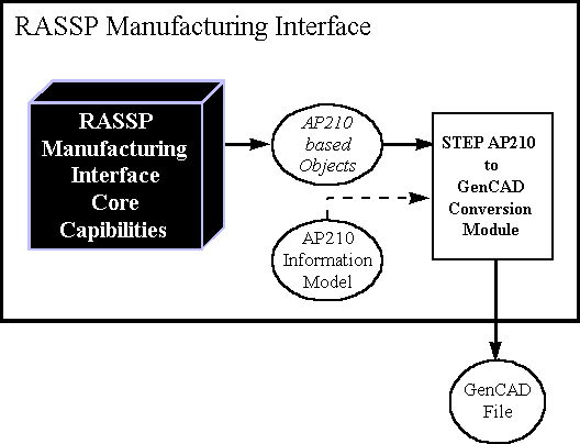
The GenCAD conversion module is available in the RASSP-MI
environment as the a2g executable. The syntax for this module is
as follows:
2.3 Manufacturing Resource Editor (MRE)
The Manufacturing Resource Editor (MRE) facilitates the capture of detailed
manufacturing process information. Once captured, this manufacturing capability
data may be used by other components of the RASSP Manufacturing Interface.
Specifically, the MRE facilitates the capture of information regarding
the following manufacturing elements:
2.3.1 MRE Operational Overview
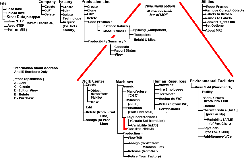
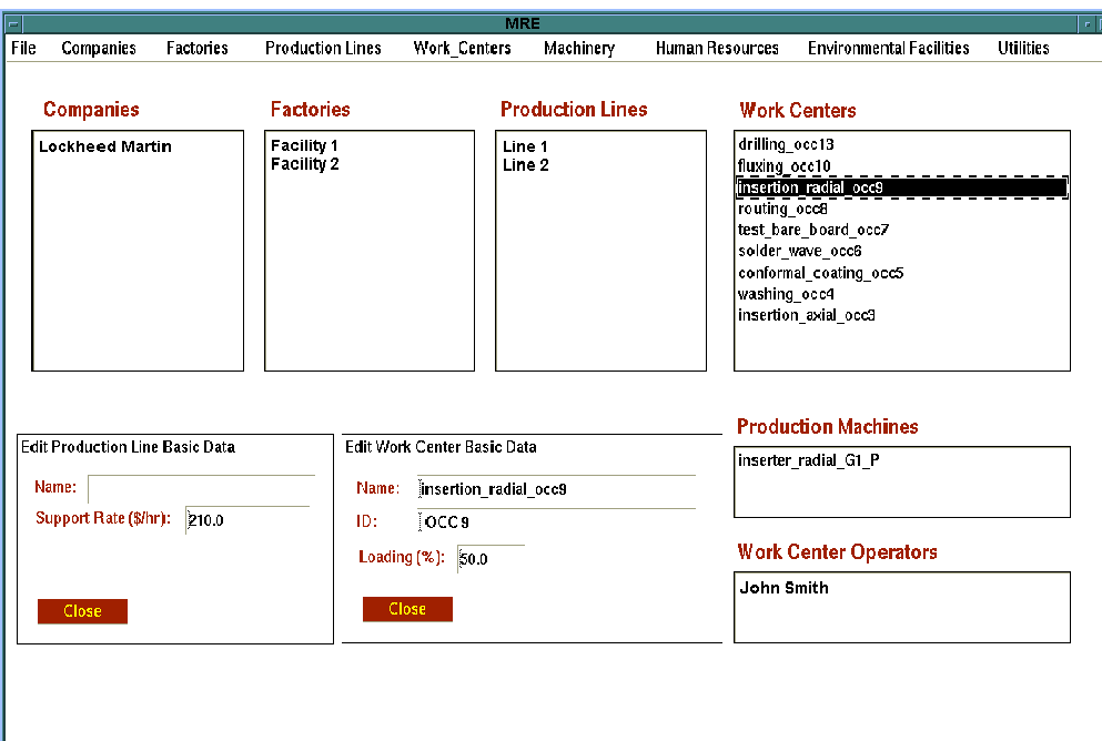
This Section discusses operational basics of the MRE. Each of the nine
Main Menu items offered by the MRE are discussed. Several menu items activate
separate data entry windows. Data entry fields within these windows may
be editable or static (i.e. informational only). Editable fields are labeled
with red text, while static fields are labeled with blue text. Multiple
data entry screens may be active simultaneously; it is not necessary to
close most data entry screens before opening another. When an editable
field is modified in one data entry screen while other screens are active
that display the same field, the displayed fields are dynamically updated.
Major Operations (main menu bar selections)
Figure 2.3.1-1 provides a hierarchical breakdown of the menu items available
from the MRE's main menu. Figure 2.3.1-2 shows the nine top-level MRE menu
selections as they appear to the user. The capabilities and functions invoked
by these menu items are discussed in this Section.
File
The File menu items provide access to the following capabilities:
Causes the MRE to read factory data from the file f_data.ob. This binary
data file contains objects in the native format of the underlying object-oriented
framework upon which the MRE is built. This underlying framework is ProKappa,
a knowledge-base product offered by Intellicorp, Inc.
Removes the current data set from the MRE. This command only affects objects
in memory. Version 2.5.9 of the MRE has a known problem related to this
command. If the user selects this command, and then attempts to Read STEP
(described below) the MRE will abort. In general, use of the Unload Data
command is not recommended.
Stores MRE data to the file "f_data.ob".
Stores MRE data to the file "f_data.step". This file conforms to the proposed
STEP AP220 factory schema definition.
Loads AP220 formatted data from "f_data.step"
Terminates the current MRE session
Companies
The Companies menu is used to define companies and virtual corporations.
The entities created with these menu items are displayed in the Companies
list box in the top-level MRE window. Companies are composed of factories.
Factories and their underlying substructure can be transferred from one
company to another. Joint ownership of factories is not supported.
Creates a new company. A dialog box appears allowing entry of company address,
multiple phone numbers, and annual overhead cost information.
Allows the user to add or change the address, phone numbers, and annual
overhead cost information of the selected company.
Allows the user to remove the selected company from the database. This
will not be allowed if the company owns factories. A company's assets must
be deleted or reassigned before a company can be removed.
Factories
The Factory menu is used to create and modify PCA manufacturing facilities.
Assets such as production machines, employees and environmental facilities
may be assigned to a factory. Assigning an asset to a factory implies that
it physically resides at the factory location and implies that the factory
"owns" the asset. Factory-owned assets may be further grouped into work
centers and production lines. Assets are initially classified as available.
When an asset is assigned to a work center or production line, it is reclassified
as assigned.
Creates a new factory and assigns it to the currently selected company.
A dialog box appears allowing entry of factory address, multiple phone
numbers, and annual overhead cost information.
Allows the user to add or change the address, phone numbers, and annual
overhead cost information of the selected factory.
Removes the selected factory from the database. This will not be allowed
if the selected factory has production lines. Factory assets must be deleted
or reassigned before a factory can be removed.
Allows the user to enter the PCA technology characteristics and type supported
by the factory.
Allows the user to assign a factory to the currently selected company.
Production Lines
Production lines are composed of two components:
Good practice values must be provided by the user. These parameters provide
the recommended operating "boundary conditions" for the production line.
Operating outside of these boundaries may be possible, but will result
in significantly reduced production line effectiveness and is not recommended.
These boundaries apply to features of PCA designs that may be processed
by the production line. An example of a Good Practice PCA layout constraint
is minimum DIP to DIP spacing. Work Centers are clusters of production
machines and employees that perform a major PCA manufacturing task. An
example of a task that a Work Center would perform is surface mount component
placement. Thus, Work Centers provide a detailed view of the machines and
employees that compose a production line, while the Good Practice values
summarize the overall capabilities of the production line.
Creates a new production line and assigns it to the currently selected
factory. The new production line inherits the Good practice "global" values
defined for the MRE session. These inherited values may be modified by
editing the Good Practice "instance" values of the production line. The
new production line's good practice values may be modified by selecting
Production Lines  Practice
  Instance Values from the main menu.
Creates an exact copy of the currently selected production line. The user
is promoted for the new production line's name. This capability is useful
for creating new production lines that are similar to an existing production
line quickly.
Allows the user to add or change attributes of the selected production
line.
Removes the selected production line from memory. All of the deleted production
line's work centers are also deleted. All of the deleted work center's
employees and machines are re-classified from assigned to available.
Allows the user to edit the "global" or "instance" Good Practice values.
The "global" values apply to the entire MRE session. When a new production
line is created, the "instance" values that apply to that production line
are inherited from the "global" values. The "instance" values apply only
to the selected production line. The following Good Practice value types
are supported:
Miscellaneous items include component orientation rules, whether fiducials
are required or not, clearance required for hand-inserted components, and
component-to-PCB-edge clearance. Switching between the three panels of
Good Practice editing screen is done by selecting one of the above items
from the Good Practice menu bar. Good Practice values must be entered
by the user. They are based on the experience of manufacturing engineers
familiar with equipment present in the production line. This feature of
the Good Practice values distinguishes them from the values present in
the Producibility Summary, which are generated by the MRE from PCA manufacturing
machine attributes.
The Producibility Summary is generated by the MRE and is based on the generic
machine function definitions that apply to the selected production line.
The generic machines that are relevant to the selected production line
are those generic machines that define the capabilities of the production
machines that make up the Work Centers that compose the production line.
Addition, deletion, or modification of one or more of a production line's
production machines invalidates the associated Producibility Summary. This
is indicated by changing the Producibility Summary's status flag from valid
to invalid. Regeneration of the Producibility Summary will update
its contents and set the status flag to valid. This is accomplished
by selecting Production Lines  Producibility Summary
  Generate from the main menu. The Producibility Summary
includes the following information:
The Producibility Summary status is shown in the upper-right corner of
the producibility summary screen. The status may also be viewed by selecting
Production Lines  Producibility
Summary
  Report Status.
Work Centers
A Work center is a cluster of Employees and Production Machines that perform
a specific PCA manufacturing task.
Creates a new Work Center and assigns it to the currently selected Factory
and Production Line. Work Centers are owned by a factory and may be used
by one or more Production Lines within the owning factory. The user may
enter a name for the new work center, or may choose a name from the provided
pick list.
Allows the user to modify Work Center attributes.
Removes the selected Work Center from memory, unless the Work Center is
assigned to multiple Production Lines. In this case, only the reference
to the Work Center within the context of the currently selected Production
Line is deleted. When a Work Center that is assigned to only one Production
line is deleted, its assigned employees and machines are re-classified
as available.
Allows the user to add an existing Work Center owned by the selected factory
to the presently selected Production Line. The Assign data entry
window shows a list of Work Centers that are not currently assigned to
the selected production line. When the user selects one of these Work Centers,
the "Machinery" and "Operators" list panels at the bottom of the window
show the Production Machines and their assigned operators.
Machinery
Management of PCA manufacturing machines is discussed in this section.
Machine definitions are called "Generic" machines in the MRE. Instances
of Generic Machines are called Production Machines. Conceptually, a Generic
Machine is a specific make and model of PCA manufacturing machine. A Generic Machine includes
all of the information necessary to define the machine's capabilities and
limits. A Production Machine is an occurrence of a Generic Machine owned
by a Factory and possibly assigned to a Work Center. Production Machines
assigned to a Work Center have a status of assigned. Production
Machines that are not assigned to a Work Center have a status of available.
A Production Machine may have an Employee assigned to it as a custodian.
Once assigned to a Work Center, a Production Machine may be assigned operators.
MRE functions that operate on Generic and Production Machines are discussed
below.
Activates the Generic Machine Configurator window, which allows
the user to create, edit and copy generic machines.
Provides a list of all Production Machines owned by the selected Factory.
Selecting a Production Machine from the list causes the following information
to be displayed:
 View/Edit
The Generic Machine and assigned Work Center information may not be modified.
The Production Machine information fields and Custodian are modifiable.
Provides a list of available Production Machines for the user to
choose from. When a Production Machine is selected, descriptive information
is displayed. If the user selects the OK button, the selected Production
Machine is assigned to the currently selected Work Center. The name of
the Work Center being assigned to is displayed in the top of this window.
Multiple Production Machines may be assigned by repeatedly selecting Production
Machines followed by selecting the OK button. Selecting the CLOSE button
terminates the window.
 Assign Machines
Removes the selected Production Machine from the Work Center to which it is currently
assigned. The machine's status is changed from assigned to available.
 Release Machines
Provides a list of Production Machines owned by the selected Factory. A
Production Machine may be retired by selecting it from the list followed
by selecting OK. Retired machines are not preserved by the MRE. Retiring
a machine is equivalent to deleting it. Before a Production Machine can
be retired, it must have been Released. Multiple machines can be
retired by repeatedly selecting Production Machines followed by selecting
OK. Selecting the CLOSE button terminates the window.
 Retire
Machines
Retire
Machines2.3.1.1.7 Human Resources
PCA manufacturing technicians and engineers are called "Employees" in the
MRE. Employees, like Production Machines, are owned by Factories. Employees
may be assigned to Work Centers as operators and to Generic Machines as
custodians. An Employee's status is set to assigned when the Employee
is assigned to a Work Center or a Generic Machine. Unassigned Employees
have a status of available.
Provides a list of defined Employees. Selecting an Employee causes the
following information to be displayed:
Definitional information includes the Employees full name, "clock" number,
labor grade, and hourly rate. Assignments to Work Centers and Generic Machines
are also displayed. Finally, skill Certifications and their expiration
dates are shown. Definitional information and Certifications are modifiable;
Assignments are not.
Allows the user to create a new Employee. A window appears and requests
the new Employee's name. After entering the name and selecting OK, a different
window appears requesting Employee information. Once the requested information
has been entered, selecting OK completes the hiring process. The new employee
are assigned to the selected factory with a status of available.
Provides a list of Employees owned by the selected Factory. An Employee
is deleted by selecting that Employee from the list and selecting the OK
button. All of the Employee's assignments must have been Released
or the delete request will be denied.
Provides a list of available Employees owned by the selected Factory.
An Employee is assigned to the selected Work Center by selecting the Employee
followed by selecting the OK button. Multiple Employees may be assigned
by repeatedly selecting Employees followed by selecting the OK button.
Selecting the CLOSE button terminates the window.
Releases selected employees from their current assignments and changes
their status to available. Assignments from which employees may
be released include assignments to Work Centers and Production Machines.
Provides a list of defined skill Certifications. Certifications required
by a manufacturing facility may be assigned to the selected Factory by
selecting the Certification followed by selecting ADD. A list of
Certifications relevant to the selected Factory is shown in the bottom
panel of the Certifications window. Employees owned by the selected
Factory may have one or more of these Certifications assigned to them.
This is accomplished by selecting the Human Resources  View/Edit option, selecting an Employee, selecting a
Certification, and finally selecting ADD. Note the Query
menu option of the Certifications data entry screen performs no function
in version 2.5.9 of the MRE.
Environmental Facilities
Management of environmental facilities (such as clean rooms) is discussed
in this section. Selecting Environmental Facilities  View/Edit from the main menu activates the environmental
facility Workbench. The Workbench supports the following functions:
Creates a new environmental facility and assigns it to the selected factory.
Removes the selected Environmental Facility from the selected Factory.
Work Centers assigned to the Environmental Facility are not deleted.
Allows the user to add, delete, and modify attributes associated with the
selected Environmental Facility.
Allows the user to add, delete, and modify the statistical properties of
a Characteristic associated with the selected Environmental Facility.
Allows the user to add or remove Work Centers from the selected Environmental
Facility.
UtilitiesThe following items are available from the Utilities menu:
Flushes the MRE's window panel cache. The first time a data entry or other
type of window is displayed by the MRE, data objects are created to support
the widgets and panels that compose the window. When the window is closed,
these data objects are not deleted. Therefore, when the same window is
requested again, it is displayed more quickly. However, if memory consumption
becomes an issue, Reset Frames may be used to clear these data objects
from memory. Otherwise, this utility should not be used as it will degrade
performance.
Finds and deleted data objects that have been damaged. This utility may
be needed if the f_data.ob file becomes damaged.
Populates the name attribute of all data objects with the type-name
of the data object itself. This exists for debugging purposes only and
should not be used by the MRE user.
Modifies the type-name of all data objects to be the same as the contents
of their name attributes. This exists for debugging purposes only
and should not be used by the MRE user.
Update and read an f_data.ob file from an older version of the MRE.
Allows the user to alter a variety of global options. The user may perform
the following tasks:
Selecting the Set Options menu item activates a workbench that facilitates
selection of available options. Once saved, these options apply for the
current and subsequent MRE sessions.
Lists the current version of the MRE and provides a brief description.
2.3.2 Data Population Constraints
Constraints exist on the order in which objects may be created in the MRE.
This section summarizes these constraints to help the user more efficiently
capture manufacturing capabilities information using the MRE.The first
objects created in the MRE must be items that can exist independently.
These include Companies and global Good Practice values. Once a Company
exists, Factories may be created. The Factory is the owner of most other
items managed by the MRE, any of which may be created once a Factory exists.
These items are listed below:
Once a Production Line exists, Work Centers may
be created. A Work Center may then have Production Machines and Employees
assigned to it.
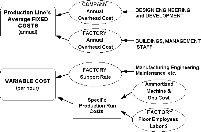
|
|
|
|
|
|
Company Overhead | Companies  Edit Edit |
|
|
Factory Overhead | Factories  Edit Edit |
|
|
Production Line Support | Production Line  Edit Edit |
|
|
Machine Operation | Machinery  Production
Machinery Production
Machinery  View/Edit View/Edit |
| Human Resources | Human Resources  View/Edit View/Edit |
The PA evaluates PCA product data within the context of specific PCA
manufacturing constraints. The use of specific PCA design and production
line characteristics enables a more precise analysis than may be obtained
using generic producibility guidelines exclusively. The PA uses product
data in GenCAD format, as do all of Mitron's commercially available products.
Within the context of the RASSP-MI, the source of the GenCAD data is STEP
AP210 (as discussed in Section 2.2)
The capabilities of the manufacturing facility are captured by the PA
and stored as parameters to a set of rules developed specifically for the
hosting facility. Using this information, the PA evaluates producibility
with respect to specific production lines and generates producibility reports.
Please refer to Mitron's documentation for a full discussion of the
operational details and capabilities of the Producibility Analyzer.
Using the Rules Definition Facility, rules can be created, edited and/or
removed. Rule meta information (concerning rule approval, origination,
description, justification, etc.) can be defined. Rule execution code,
premise and conclusion components, can be created and edited using context
sensitive menus. The rule premise component, or "IF" statement conditions, define
what actions are required before the rule conclusion component is executed.
The rule premise consists of logical combinations (ANDing or ORing) of
system functions. System functions include: storing temporal information
to the database (facts), storing permanent information to the database
(object attributes) and providing feedback to
the user in the form of messages and issues. The conclusion component consists
of actions to take as a result of all of the premise conditions being met.
The rule conclusion is a logical combination (ANDing) of system functions.
The Bachus-Naur Form (BNF) grammar description provided in Figure 2.5.1-1
defines the rule definition format.
Note that a rule conclusion can include the storing of facts and/or
object attributes (system functions). A rule premise may include functions
that test facts and/or object attributes. Utilizing the two preceding capabilities
allows one rule to call another rule. This process is known as 'chaining'.
This ability can be used to capture the intent of a multistage rule with
several smaller rules. Additionally, it allows the system to continually
ask new questions when the answers from other questions support information
needed by the new questions.
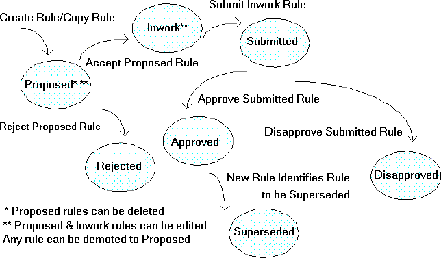
The Rules Definition Facility organizes rules by status and set. Rule
status defines the progress of a rule in the process of defining, submitting
and accepting rules. Rule sets are user defined categories that aid in
organizing rules into small, meaningful groups. In the RDF, rules are selected
either by their current status or by the rule set that they belong to.
When rules are first created their status is initialized
to proposed. A proposed rule contains only meta-data about
the rule (its description, justification, etc.). Note the Rules Definition
Facility allows the user to input rule detail via the Rule Edit Panel on
a proposed rule. Proposed rules are the only rules that can
be deleted.
A proposed rule can either be accepted or
rejected. If the rule is rejected, rejection information is requested,
its status is changed to rejected and the rule can no longer be
edited. If the rule is accepted, its status is changed to inwork
and the rule can be edited. Inwork rules are typically used in conjunction
with the Rules Execution Facility in an edit/execute/ cycle. Once editing
is completed on an inwork rule, it can be submitted for approval
or disapproval. The status of the inwork rule is changed to submitted
while the approval process is taking place. If the submitted rule
is disapproved, disapproval information is requested, its status is changed
to disapproved and the rule can no longer be edited. If the submitted
rule is approved, its status is changed to approved. If an approved
rule has defined a rule that it supersedes, then that rule will have its
status changed to superseded. Any rule can be demoted to proposed
by using the demote rule menu selection. Figure 2.5.1-2 depicts the state
diagram that shows how the state of a rule may change over time.
A rule can belong to any number of rule sets. When rules are executed
in the Rules Execution Facility they must first be selected via rule set.
Figure 2.5.1-3 depicts an example of a rule set hierarchy and its associated
rule sets.
2.4 Producibility Analysis
The Producibility Analyzer (PA) used within the RASSP-MI is a commercialized
version of the Producibility Advisor. The Producibility Advisor
was developed as part of a previous, government funded effort and significantly
enhanced as part of the RASSP Manufacturing Interface effort. The Producibility
Analyzer is commercially available from Mitron Corporation.
2.5 Rule Definition/Execution Facility (RD/EF)
To pose and act on multi-domain questions, facilities were developed to
define and execute Design For X (DFx) rules. A Rules Definition Facility
(RDF) was developed to define generic DFx rules. A Rules Execution Facility
(REF) was developed to execute the defined rules against STEP Application
Protocol data.
2.5.1 Rules Definition Facility
The Rules Definition Facility (RDF) is a database editor designed to assist
engineers in capturing PCA related design and manufacturing process knowledge
in the form of rules. The rules are stored in an object oriented database
for future use in an integrated knowledge based framework or system.
<rule> ::= <premise>
<conclusion>
<premise> ::= <complex
clause> { Or <complex clause> }*
<complex clause> ::= <simple
clause> { And <simple clause> }*
<simple clause> ::= <system
function> <function parameter>*
<conclusion> ::= <simple
clause> { And <simple clause> }*
<function parameter> ::=
<simple clause> | <constant> | <variable><variable> - Alphanumeric
pattern instantiated as object when rule is fired (e.g. component1,
layer2, net3).
<constant> - Number, Integer
or Floating Point
<system function> - Any
system provided function that returns a value for
testing or comparison (e.g. logical, math)
Note: This Backus-Naur Form has been extended using the Kleene cross (sequence of one or more)
and the Kleene Star (sequence of zero or more).
Information defined in the Rules Definition Facility can be stored
in the database and later executed using the Rules Execution Facility (REF).
To simplify the task of defining and executing rules, the Rules Definition
Facility provides for the organization of rules into rule sets. A rule
set is a group of rules that share a common subject. Rule sets are arranged
in a rule hierarchy. The rule sets and their hierarchy are defined by the
user. As an example, a user may wish to define a set of design rules. Subsets
of rules under the design set could be analog, digital and mixed.
| Rule Summary Type | Description |
| Individual Rules Attempted | Number of different rules that are attempted |
| Individual Rules Succeeded | Number of different rules that succeed |
| Total Rules Attempted | Total number of rules (some rules are counted more than once) that are attempted |
| Total Rules Succeeded | Total number of rules (some rules are counted more than once) that succeed |
An integral component of the interface is the Citrix Winframe server
software, which extends the capabilities of Windows NT. The Citrix Winframe
technology acts as a redirectable layer between Windows NT applications
and the Windows NT rendering layer. On the server machine, an application's
display calls are intercepted by Winframe and redirected to a remote client
machine. A Citrix compliant plug-in must be running on the client machine
to interpret the incoming data stream and generate the application GUI.
The plug-in for Windows 95 and Windows NT is freely available at http://www.citrix.com .
The plug-in for UNIX is available for a nominal fee. The Winframe server
is built into the operating system; a special version of Windows NT modified
by Citrix must be purchased for the server machine.
Once the Citrix client plug-in is installed, the Producibility Analyzer
can be accessed from a site hosting the RASSP Manufacturing Interface.
The RASSP-MI can be installed such that its capabilities can be accessed
via the Internet, or only through the corporate intranet.
For more details on the technology underlying the web-based interface
and a discussion of alternate approaches to providing remote access to
RASSP-MI capabilities, see [SCRA97].
2.6 Web-based interface
The web-based interface to the RASSP Manufacturing Interface enables users
of the system to access the capabilities of the RASSP-MI remotely. The
implementation is currently limited to providing remote access to the Producibility
Analyzer, but can be extended to include other subsystems of the RASSP-MI
in the future. Figure 2.6-1 shows the architecture of the web-based interface.

![]()
![]()
![]()
![]()
Next: 3 RASSP Manufacturing Interface Usage Scenarios
Up: Appnotes Index
Previous: 1 Introduction